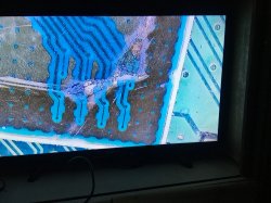
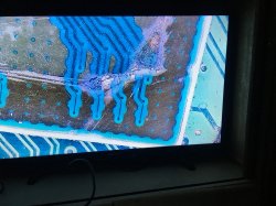
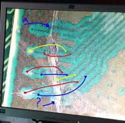
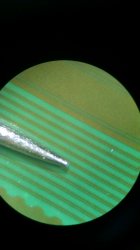
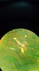
The 5th picture (the one with the soldered wire to the lines/traces) makes me curious. It appears the lines all communicated to each other (I assume hence why
@ElGris has soldered from one head to the next line across) and it doesn't have any side effects(yes, having metioned all the dots represent the ground plane).
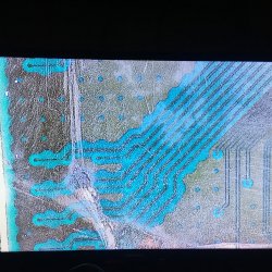
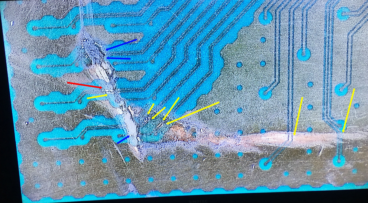
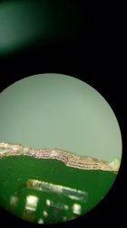
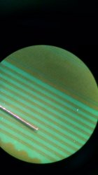
Actually those traces (even if they're in parallel) are different, they're not the same. I didn't mention that this picture:
https://www.psx-place.com/attachments/img_20200206_082124511-jpg.35306/
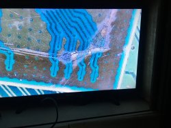
Belongs to a CECH-C that I repaired right after the G I posted the last year, so this is a different fix, but same issue, two traces cut. CUT!!!

I know the picture where I shared the second fix is confuse, it has kapton tape on it, but what I wanted to clarify is that those traces are different, in that case, if I remember well, one trace needed a jumper (which is the big wire you see), the other one just a soldering point, but as I know that's complicated (even at funny sizes like these), I think I added a second small jumper over the second trace, which looks intact but it was clearly cut, because that C was giving me still GLOD.
I recommend you
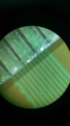
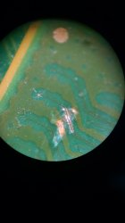
@K112 to use a small needle to remove the protection on the traces/heads if you don't have a scalpel, and please use a good scope, because is really difficult if you can't see anything.
@sandungas knows all the story, really funny btw

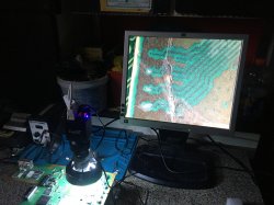
I used a crappy soldering iron, a low cost microscope (cheap but at least is not digital, really important), wire that I don't even know what size it is (I grabbed it from an old chinese alarm clock, since the jumper wire I had was thicker) and cheap ass flux (really cheap).
From all of this, the most important thing is the scope, like I said, you need to see what you are doing, if you really want to accomplish this.
I want to improve it though, since I still have this C in a box (I also want to rework it), just need to get the right tools. And then, the spaguetti is going to evolve
it seems the problem was the wire, he was struggling with it because was not attaching to the trace
/
Actually it was EVERYTHING LOL. The one that put his ass to do it with the crap tools I had at the time will understand
Btw,
@K112 my method in every soldering is to apply flux and "paint" with tin the traces I need to solder, that in this case were two, and two heads. Once the soldering points are "tinned" with the iron, you need to tin the wire, by just grabbing some tin with the tip of the soldering iron and make contact in both sides of the jumper. With the iron I have the only way to solder small jumpers like this is putting the tip over the wire and make some pressure for and instant. Not too much, else the other side of the jumper will loose.
As last comment, these are spaguetties 'cause I couldn't cut jumpers small enough to be able to grab them with the tweezers. And while the job was done, and I'm sure it was firm, I didn't want to cut anything with the scalpel, 'cause my scope hasn't a good zoom for this job. If you want to do it like a pro, you need barlow lens.
I wish you good luck


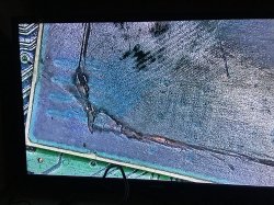
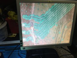
 , it's a matter of hit and miss.... the console has not been used in 2 years, and as everyone suggested to use a painters knife and heat....But I went without the heat and used it blunt, no flatting it with sandpaper (think 800 grit and 1200 grit will be just fine) and scratched twice and thus as a result ended with this
 .
. , the wire mentioned in the link is 0,01. Buying from Aliexpress unffortunately will not work (as of present) till /bans/embargoes/ taxes are lowered and removed in the country i'm in.