manples
Member
Well, I think I completely deserve it.
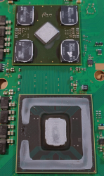
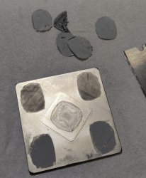
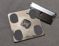
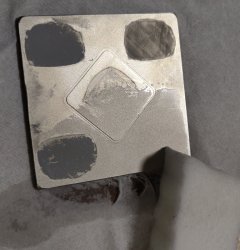
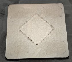
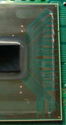
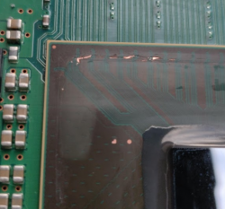
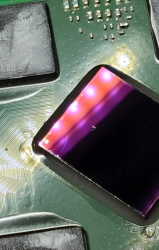
I did not use a painter's knife but a badly sharpened nail file because I was too impatient. And for the exact same reason, I popped the RSX lid after unsuccessfully attempting to cut the old paste between the ram chips and the lid... maybe not obvious in the picture but there's a spot on the RSX die, and a crack as well (that little curvy thing is unfortunately not a speck of dust...).
I hate myself. I had that PS3 for 12+ years and recently put a 1TB SSD in. It was fully loaded with everything up-to-date and working, all was great except for that damn fan that I wanted to shush down.
Lesson learned.
(in a desperate last move, I tried the heat gun trick hoping that would change something, but of course, no)
") i face same (random) "flashing red light 3 beep" Fan problem .. but ... i have successfully delid both CPU & RSX seems problem persists & get randomly "false" overheat protection .. i have no clue about my before delid temps .. but now thy are low : Fan 30% CPU 50 RSX 53 after 1 hour game play
i face same (random) "flashing red light 3 beep" Fan problem .. but ... i have successfully delid both CPU & RSX seems problem persists & get randomly "false" overheat protection .. i have no clue about my before delid temps .. but now thy are low : Fan 30% CPU 50 RSX 53 after 1 hour game play