sandungas
Developer
I ilke the idea of creating a jig for the cutting wire, the goal is to adjust the position of the wire very accuratelly and also to simplify the work (handling the wire with our hands is a pita because is the kind of work that takes lot of time)You just gave me an idea for a special jig for using with that molybdenum wire you're talking about. I'm thinking some kind of jig to hold an RSX with a screw knob that the wire mounts to. Pop the chip into the jig, screw down a second half of the jig to hold the chip firmly in place and then turn the screw to apply even tension to the molybdenum wire so it cuts evenly into the thermoglue of the RSX.
This is kinda an early WIP but maybe shows what I'm trying to describe a bit. The two channels will be for the molybdenum wire.
<Edit> I updated the design which shows what I mean a lot better. The idea is to turn the RSX upside down, so BGA pad side facing up and hook the molybdenum wire between the IHS and the VRAM modules and to two posts on the gears on the right hand side.
After that place a cover I've yet to design over the top, clamp it down and screw down a small plastic bolt to hold the RSX firmly in position. Finally, use the wheel to tighten the molybdenum and slice right through the thermoglue on the RSX VRAM modules.
But i think there is a problem in your design, in the way how is aligned the wire you are trying to cut one side of the square... or better said you are trying to cut 2 corners + 1 side all together
Thats a problem because is going to generate too much friction
What we need to do is to start cutting in the weakest point (a corner) to minimize the friction, after that we need to rotate the jig 90º to cut other corner, and so on
In other words, the jig should be re-attached 4 times to the RSX in 4 different positions
While thinkinig in it i started drawing it with pen and paper
 (i had to review it 2 or 3 times), i dont have any cad design app, but i made a dirty sketchup in photochof
Is not finished though... still open to more improvements, i have not dedicated much time to it but i think it can be made in a 3D printer with plastic

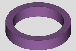
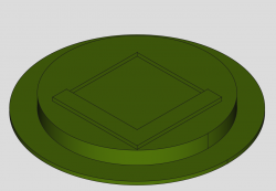
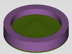
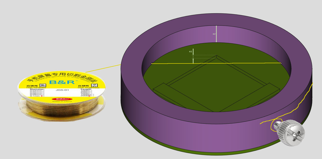
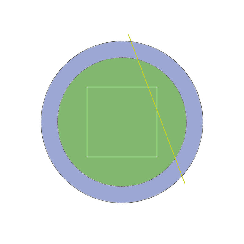
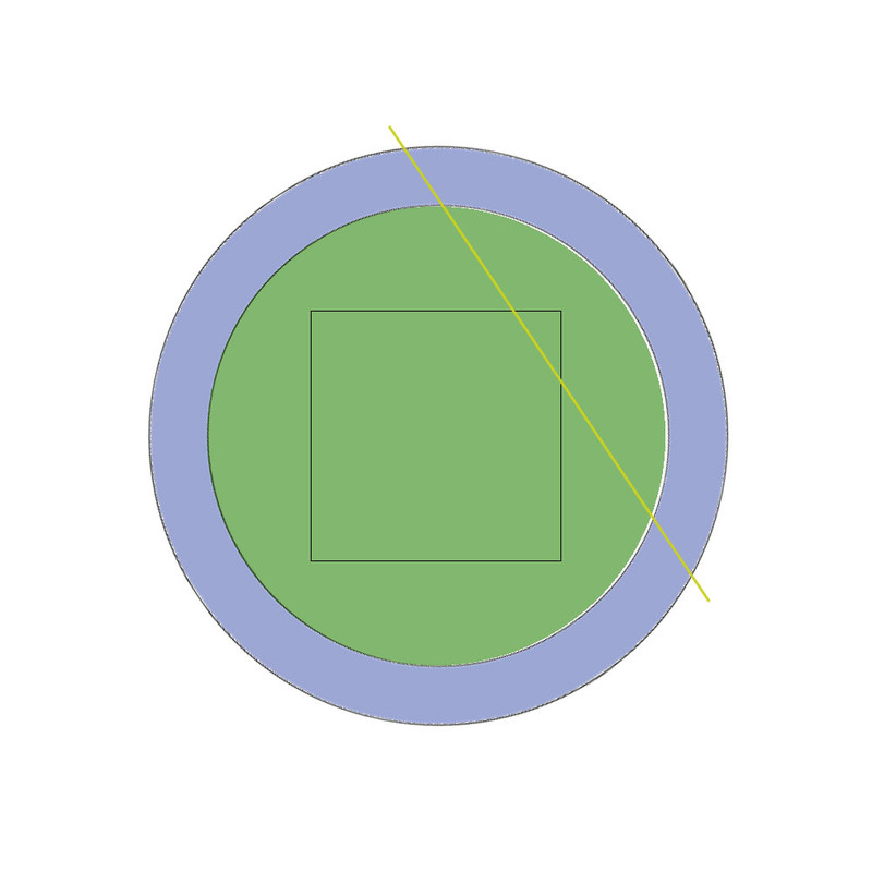
The geometry is simple, is just an square inside a circle, and is composed by 2 pieces... the external piece is a "ring" because i want to be able to hold the ring with a hand and rotate it back and forth to create the "sawing" effect
The depth of the square is the thickness of the IHS (upper side of the IHS)
The 2 little holes of the ring are intended to insert the wire... by now i have not though in how to attach the wire to the ring, but keep in mind we just need to hold one of the extremes of the wire to one point of the ring. The other extreme of the wire doesnt needs to be fixed, we can grab the wire roll/tape with a hand
Last edited:
")

")

