finalman
Member
I'm currently designing two adapter PCBs for FAT model PlayStation 2's so that I can convert front panel buttons, LEDs and disc drives between PS2 FAT model revisions v4-8 to v9-11 and vise versa.
I need some help with the component selection as I'm only a beginner at the electrical stuff.
Technical details:
The PS2 sends 3.5v up the disc eject LED rail/trace to a NPN transistor base to connect 12v to GND to turn on the blue LED.
Now early v4-8 PS2 FAT models have a NPN transistor on the power/eject/LED PCB when the eject LED signal leaves the motherboard it can either be 3.5v (LED on) or 0v (LED off). Later model v9-11 PS2 FAT models have the transistor on the actual PS2 motherboard so when the eject LED signal leaves the motherboard it can either be 0v \ grounded (LED on) or not connected (LED off).
So on v9-v11 PS2s models when the LED rail is grounded I need to invert the signal to send 3.5v (3.3v and 12v are is accessible from my adapter PCB), so that 3.5v goes to the early v4-8 model PS2s power/eject/LED PCB's NPN transistors base pin.
So what PNP transistor in a SOT-323 package, resistors and any capacitors should I use.
I've already designed the adapter for v4-8 PS2 FAT motherboards to use late model PS2 power/eject/LED PCBs. All that I did was add a NPN transistor between input and output connectors, plus a resistor and capacitor.
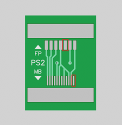
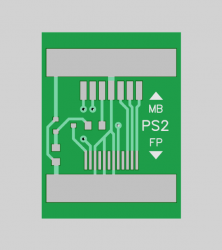
Pictures attached. Other Picture is of the incomplete v9-11 PCB. Red rectanges are the two LED signal pins.
Also If anyone else is interested in building a Frankenstein PS2 from mismatched model revision parts see my blog here for hints on what you can do.
I need some help with the component selection as I'm only a beginner at the electrical stuff.
Technical details:
The PS2 sends 3.5v up the disc eject LED rail/trace to a NPN transistor base to connect 12v to GND to turn on the blue LED.
Now early v4-8 PS2 FAT models have a NPN transistor on the power/eject/LED PCB when the eject LED signal leaves the motherboard it can either be 3.5v (LED on) or 0v (LED off). Later model v9-11 PS2 FAT models have the transistor on the actual PS2 motherboard so when the eject LED signal leaves the motherboard it can either be 0v \ grounded (LED on) or not connected (LED off).
So on v9-v11 PS2s models when the LED rail is grounded I need to invert the signal to send 3.5v (3.3v and 12v are is accessible from my adapter PCB), so that 3.5v goes to the early v4-8 model PS2s power/eject/LED PCB's NPN transistors base pin.
So what PNP transistor in a SOT-323 package, resistors and any capacitors should I use.
I've already designed the adapter for v4-8 PS2 FAT motherboards to use late model PS2 power/eject/LED PCBs. All that I did was add a NPN transistor between input and output connectors, plus a resistor and capacitor.
Pictures attached. Other Picture is of the incomplete v9-11 PCB. Red rectanges are the two LED signal pins.
Also If anyone else is interested in building a Frankenstein PS2 from mismatched model revision parts see my blog here for hints on what you can do.
Attachments
Last edited: