PS4/PS3 hardware fan accelerator

vyktormvmpay25

Senior Member
Hello
Thank you so much everyone. This is my fan accelerator module which is compatible with ps3 and ps4.
This is for advanced users and developers. Should know well basics of electronics before starting this project or finding someone who knows.
Just swapping grey pin(pwm) with brown (12v), module will be compatible with both ps3 or ps4 .May be compatible with other fans with pwm signal 3v3. Developed in two ways.
First release will be with manual programmable micro switch which is bit more expensive.
Programing and schematic are on this link
http://s.go.ro/3as4ew79

I wish this can be edited by any admin so it can be as tutorial. Don't have to many options from phone. I will try to answer your questions in reasonable time.
I will edit by time each part value.
First design.
Two caps 1uf25v pitch 1206 smd.
Five resistors 10k 1206 smd.
Voltage regulator Ams 1117 3v3.
Ic Atmel Attiny 45 wsop or any bigger measure.
On first model Attiny 45 must be programmed out of board direct connected to programmer.
First load hex file on attiny 45, then program fusebits.
If loading schematic from my link in a pcb design software may get different design.

083de940358dab73b6d0c40b2a0508f9.jpg
790cf41bbcbe8ce41ba8b8baadf2394f.jpg
e4b83ab8253a40607713535c909c6d65.jpg


656bf13ec7abc43cfe7d5ea30312221b.jpg


Second module will be programmed via isp points with 12 v external power.
This module will not have programmable switch but will have hex for each stage of fan increased by 10%.
Update on V2 is out on same folder as v1 but here is link

http://s.go.ro/3as4ew79
Untitled2.jpg

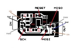
C1,C2 1uf/25v smd 1206
R1,R2 10k smd 1206
PU1 Asm1117 3v3
IC1 Attiny45 used tssop8
ON PROGRAMMING V2 RESET PIN MUST BE ENABLED .NOT LIKE V1 WHERE PIN WAS used as digital imput.
 

Attachments

  • Untitled.jpg
    Untitled.jpg
    69.1 KB · Views: 161
Last edited:
Thread sticked, this project is really nice, keep the good work :encouragement:

I have a fan accelerator like this one, bought in ebay years ago, it looks you got your inspiration from the same shop where i bought it :D
 
Last edited:
Btw, im happy to see an open source project to build this at home
You should prepare a "minimal version" to etch the circuit board in the smallest size posible and in the cheapest way, without connectors, and even without the roulette

Just keep the pads of the roulette and the user needs to bridge them with a wire to configure the speeds multiplyer.. actually, in my experience i can tell the roulette is a bit pointless because what you are going to do the first day you connect it to the console is this:
1) Make some test playing games to find the value you need to enter in the roulette
2) Move the roulette an unit up or down
3) Make some more tests playing games
4) Dont move the roulette ever again

With this i mean... the roulette is only useful the first day you configure it... but after that you dont really need the roulette anymore
Also, the range of values we are supposed to select from the roulette is very limited, most people only needs a +1, +2, or +3
I dont think much people is going to need values bigger than +4 or +5... and i dont expect anyone to use the higest values like +8 or +9
 
Last edited:
Many thanks ! As @sandungas said many people will need 50% or 60% so I will update version 2 of this model!
Edited
NOW all are on same link up on first post.
Remember if use for ps4 just swap pwm pin/cable gery with brown power12v
PCB sizes for v2
9a56599009afe2c4e95bc4185a0a40eb.jpg
1c7a84ef2d60ca1cf16a71956d0dfa9c.jpg
 
Last edited:
Which kind of algorithm are you using to calculate the final speeds ?
I think the device i have is using the value of the roulette as a scale factor in a scale from 1.0 up to 1.9

Lets say i configure it in value +5 (and it represents an scale factor of 1.5)
-When the motherboard sends speed 10% to the fan... the device converts it to speed 15% (10*1.5)
-When the motherboard sends speed 20% to the fan... the device converts it to speed 30% (20*1.5)
-When the motherboard sends speed 30% to the fan... the device converts it to speed 45% (30*1.5)
-When the motherboard sends speed 40% to the fan... the device converts it to speed 60% (40*1.5)
-When the motherboard sends speed 50% to the fan... the device converts it to speed 75% (50*1.5)
-And so on...

This is why i said some of the values of the roulette in my device are pointless because are going to boost the speeds out of the range (resulting in speeds bigger than 100%). In that case the device should set the PWM signal to the max
The problem is if this happens too soon, in the example im using in this post using scale factor of 1.5 im a bit at the limit because scale factors bigger than 1.5 are excesive
 
Well, im not sure if what i said in my previous post is right, i could never meassure it so i dont really know
What i said in my previous post increases the speeds exponentially, but maybe it just does a sum and every unit of the roulette represents a +10%

So... lets say i configure it in value 2 (and it represents a +20%)
-When the motherboard sends speed 10% to the fan... the device converts it to speed 30% (10+20)
-When the motherboard sends speed 20% to the fan... the device converts it to speed 40% (20+20)
-When the motherboard sends speed 30% to the fan... the device converts it to speed 50% (30+20)
-When the motherboard sends speed 40% to the fan... the device converts it to speed 60% (40+20)
-When the motherboard sends speed 50% to the fan... the device converts it to speed 70% (50+20)
-And so on...

Dunno, are 2 different ways to do it
 
Yes like you say @sandungas all hex represent percent added by 10% from what motherboard give you out .If cold unit is 20% of fan speed and add hex 50% as example, you will get like 70% of fan speed which is not loud and keep unit cold in game .
Basically keep as start that 20% from motherboard on cold unit.All are controled on same way at sony.The difference is capacity of air from fan.
Probably yours is going up with 15% from base point of 20%
Some 2000 series from time to time may reach next stage of temperature but still not loud.On ps4pro , after reball , in game I get 52 degrees with hex 50% in one hour. Thermocouple seated on bottom of APU center . Usually without fan accelerator I get 85 degrees .
It depend on unit and refurbishmet is made like reball delid etc .Old electronics still hard to keep them cool , they were desingned consuming power= hoter.
 
Last edited:
Could one of those attiny85 boards be used as the base for this project or Arduino mini?
Like the Digispark Attiny85 based for sale on ebay.
 
Last edited:
Usually yes but you have to do sketch for it.
Can be any as long you can compile source code to work as pwm for fan. It depends how many imputs you want to use. The simplest will be programmed without micro encoder.
 
Could one of those attiny85 boards be used as the base for this project or Arduino mini?
Like the Digispark Attiny85 based for sale on ebay.
Btw, dont get scared about the challengue of "etching" the circuit board at home (i made some and i know a few tricks to do it easy, eventually we can talk about it)... the fact is we dont need the circuit board :D

I mean... to build the "simple" version of this project are only needed 5 components, the atmega chip, a couple of resistors and a couple of capacitors
Is posible to solder the components directly to the atmega pins, and with each others directly... then cover everything with a big blob of silicone to isolate everything (and additionally inside a shrinking plastic tube for a more professional look), and thats all

The guetto style ftw... for a project like this it should work, ive seen others made that way too and the result is aceptable (specially because the final "device" is going to be tiny)
 
Assembling this electronic board is very easy. The issue is cost. For ebay an ATTINY 85 Kickstarter board costs less than two euros and comes with the built-in programmer.

The Specs:
1. Support for the IDE 1.0+ (OSX/Win/Linux).
2. Power via USB or External Source - 5v or 7-16v (automatic selection).
3. On-board 150ma 5V Regulator.
4. Built-in USB (and serial debugging).
5. 6 I/O Pins (2 are used for USB only if your program actively communicates over USB, otherwise you can use all 6 even if you are programming via USB).
6. 8k Flash Memory (about 6k after bootloader).
7. I2C and SPI (vis USI).
8. PWM on 3 pins (more possible with Software PWM).
9. ADC on 4 pins.
10. Power LED and Test/Status LED.

https://www.ebay.es/itm/1x-Digispar...913408?hash=item446fa5ce80:g:EWoAAOSw3L9fn3Kf
 
According to the datashep of the ATtiny25 /45/85, they operate between: 2.7 - 5.5V between 0 and 10 Mhz and 4.5V 5.5V between 0 - 20 Mhz. The ps3, I suppose it delivers 12V through pin 2. If necessary, it would be easy to change the AMS1117 5 for a 3.3. One thing in the schematic, starting from bottom to top, In is Pin 1 PWM signal, pin 2 voltage input, pin 3 ground? (I assume the square is pin 1).

•Operating Voltage– 1.8 - 5.5V for ATtiny25V/45V/85V– 2.7 - 5.5V for ATtiny25/45/85
•Speed Grade– ATtiny25V/45V/85V: 0 – 4 MHz @ 1.8 - 5.5V, 0 - 10 MHz @ 2.7 - 5.5V– ATtiny25/45/85: 0 – 10 MHz @ 2.7 - 5.5V, 0 - 20 MHz @ 4.5 - 5.5V
 
Yes square is pin 1. Now if you look at that blue board you have to cut parallel 5v from usb if you willing to sell other ppl or they can damage ps3 pushing 5v instead 3v3. May need to cut 5v vcc from usb line and put it on imput of ams 1117 but you can program like this without fan or ps3 motherboard connected . It's a bit complicated with it if you are not careful
 
Hi,
Which is the frequency of the pwm signal for the ps4 fan?
I was thinking to implement it on esp32 c3 mini board... to which i much more at ease than the attiny.
 
Hi,
Which is the frequency of the pwm signal for the ps4 fan?
I was thinking to implement it on esp32 c3 mini board... to which i much more at ease than the attiny.
I've talked with al azif about fan speeds on the ps4. we both agree that they're good enough at stock. the only time I can see a problem, maybe, is with a ps4pro. I've heard those get very hot. I can just image a ps5 pro at this point. lol
 
Back
Top