PS3 Syscon fan settings (Coordinate Graphs)

Ok, i found it :)
There is a detail of his structure in wiki that i dont get, how is posible to have a "data size" of 0x0FAA ?
At which absolute offset i need to start counting that size ?
And the patch region ends at 0x3000 ?

Not really, since it doesn't involve anything special.
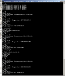
You install the patch and then you can use the 'extend' UART command to dump the firmware (@ 115200 baud).
Doesn't effect the console at all.

Yes, I have that on my list but I'll only do it one time (and we're still missing at least 1 soft id).
Hmmm, ok, i was thinking only in the 8 custom patches to override the 8 official patches but you want to include custom patches for the other syscon models that never had an official patch published
And with the info we have is only posible to include a total of 14 patches... but you want to include at least 15 (with the SW-302)... or 16 (with the SW3-303)
We dont know the softid of that 2 syscon models, and the softid is used to enrypt the patch, so by now is imposible to create that 2 patches
If thats the plan, yeah i like it a lot and i understand that decission of doing it only after we find the complete list of softid's

The SW-302 is something common, right ?, there must be people with a CECHLxx, CECHMxx, CECHPxx, CECHQxx (VER-001 motherboard) with it, is just they never reported his softid
And the SW3-303 is chronologically aligned with the misterious NPX-001/NSX-001 and the unknown "chassis type" 0x13 and 0x14 that seems to use the arcade keys... sooo... maybe we will never find a SW3-303

In short... it makes sense to wait a bit for the SW-302 but waiting for the SW3-303 is not worthy, right ?
I didn't work after exchange, 1200 is out, only 2130 error but now with 3 beeps. Probably cpu curved in middle and losing connection when I've heat to exchange. It will work after reball. If same error I will test exterior thermocouple as you say. I thinked for that, but first I want to see reball test to be more confident. Now I have left it aside, got another for reball with no errors or putty sb debugging, can hear recovery beeps.
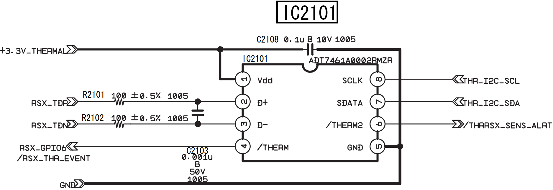
Yes about TMP411A for CELL and TMP411B for Rsx you are right.
0099d2c24c79a6d51fce7fc0c54af650.jpg
42925c671a36e06c0b04795d4c1aaae0.jpg
Imagine the only problem of CELL is that his internal thermal sensor was fryed by a huge overheating... reballing it is not going to fix it... and maybe the CELL can work fine under normal workload (while playing a game)... you dont know if is stable because the PS3 doesnt boots so you cant stress it
Or lets say... the only problem is a single BGA ball broken (what a coincidence, the pad for the thermal sensor, heheh)
In that case i would do the "ghetto fix" i mentioned in the previous post to make syscon happy and you will be able to boot the PS3, install a firmware, and see if CELL is working fine

Btw, have you checked if the 75ºC in less than 1 minute you reported before is real ?
I mean... by meassuring the CELL temperature externally, with the probe of you reball station, or a infrared gun, etc...
You know... is needed to keep an eye at the UART [SERV THERM], and at the same time check the CELL temperature by other means
If the temperature is not real i would not care much because it means CELL is not really overheating, i would do the ghetto fix i mentioned in my previous post, you said that you only want that motherboard to use it for other experiments, so that fix is good enought

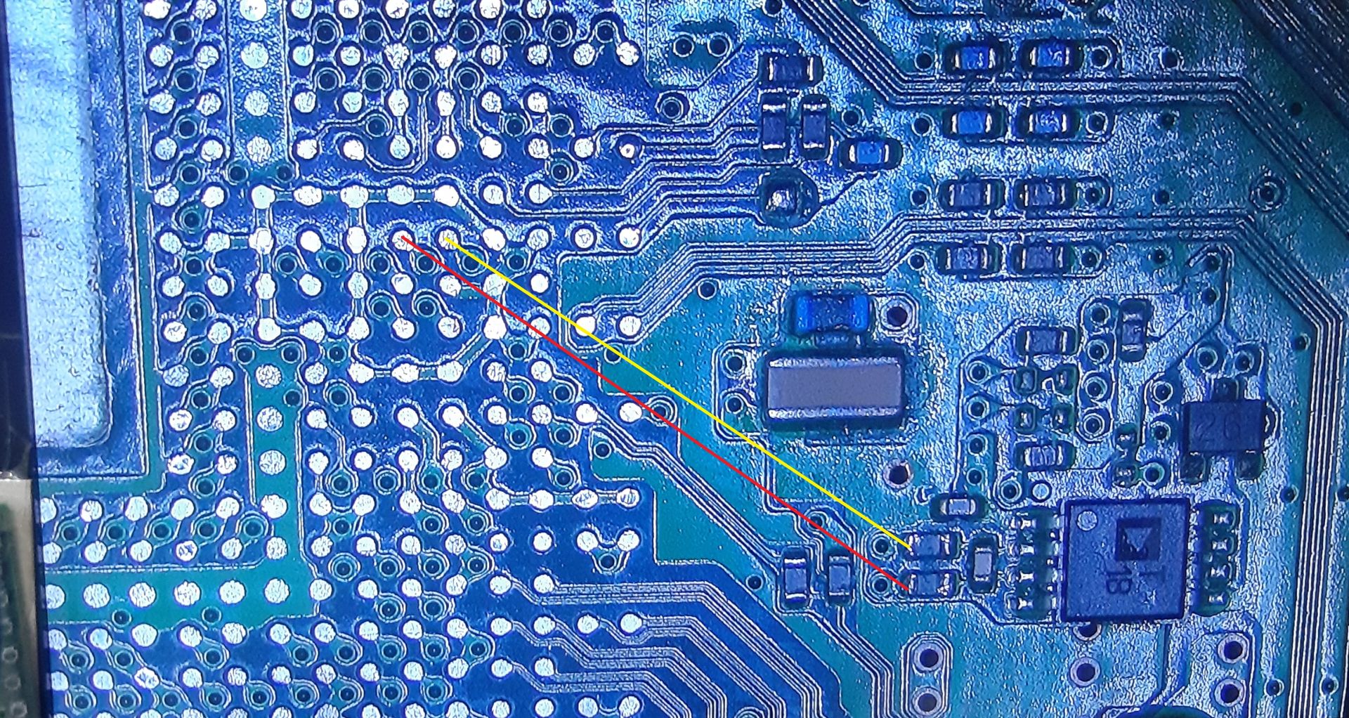
And another btw, in between the thermal monitor chip and the thermal sensor inside CELL there are 2 resistors and 1 capacitor, you should check them
IC2101_RSX_Temperature_Monitor.png


---------
Thx for the confirmation about the thermal monitors 411A/B used in DYN-001, this details eventually could help a lot :)

Eventually i will add this info in wiki here but im going to make a dirty list of the motherboards in groups based in the "unk_2" and "unk_3" values found in the official thermal configs (that seems to be related with the thermal monitor chips)
If you have some time, please take a look at your pile of scrap boards to help me complete this list (at least the superslims), right now i think most probably all the slims and superslims motherboards are using the texas instrument TMP411A (CELL), TMP411B (RSX)


COK-001, COK-002, SEM-0001 = AD51/067ARMZ-REEL (CELL), ADT7461-D (RSX) (this models have some more for BEVR, EEGS, SB)
DIA-001, DIA-002, DEB-001 = ???
VER-001 = ???
DYN-001 = TMP411A (CELL), TMP411B (RSX)
SUR-001, JTP-001, JSD-001, KTE-001, MSX-001, MPX-001 = TMP411A (CELL), TMP411B (RSX)
NPX-001 = ???
PQX-001, PPX-001, RTX-001, REX-001 = ???
 
Last edited:
I will also add pinout to each cpu from now on. It seems kind of thermal diode inside, only in one way can get measured kind of value of 687 on dyn001 and a jtp cpu . No resistance up to 20 mega ohms. Measuring on cpu pins out of board. It can be measured on board by taking out those two resistor in front of ic imput , traces are straight. I will add /edit on cpu photo pinout with time.
Already desoldered but got something to do and may take time for results. As I've already desoldered only cpu, no pins corrosion seems fine on cpu side
e86a9700b536570026420dfd4d6ec7b2.jpg
Now if I presume right it should be rsx that will always fail on the side with more pressure. Never suggested penny trick or pressure, even like that will fail with time on those corners even untouched units.
Usually on this side gpu is not starting and boards are in glod state, some can hear recovery. Second though I see something as someone tried to read rsx tmp ic as and eprom!? Some sing of a clamp on his pins. Not really sure never looked to close to those ic. This way to diag on pc came as new thing for most of us.
b10870bfe0778031f544f223994a33aa.jpg
The pressure exists but opposite, this should be ram power. Also 2 pins in communication line cpu/rsx.
We will see after reball.
eda6f7c1a7be905fb3d1510650655a20.jpg
5900534664afef7c3a6774c5c40ecc8a.jpg

027ccebd2ccf8ab7522aa18b45222cf3.jpg

a1c98a89a1c1124cd14bee3f1965d528.jpg
 
Last edited:
Ok, i found it :)
There is a detail of his structure in wiki that i dont get, how is posible to have a "data size" of 0x0FAA ?
At which absolute offset i need to start counting that size ?
And the patch region ends at 0x3000 ?
The data size starts counting at 0x16. The complete patch size is 0xFC0, Sony reserves 0x1000 on the Flash.
However 0x16+, 0x18+ and 0x9A+ are ignored on the SW (only used on SW2/SW3).
The region after the table is partly parsed on SW2/SW3, but in general that's the area where you store the code you want to patch in using the table.

Hmmm, ok, i was thinking only in the 8 custom patches to override the 8 official patches but you want to include custom patches for the other syscon models that never had an official patch published
And with the info we have is only posible to include a total of 14 patches... but you want to include at least 15 (with the SW-302)... or 16 (with the SW3-303)
We dont know the softid of that 2 syscon models, and the softid is used to enrypt the patch, so by now is imposible to create that 2 patches
If thats the plan, yeah i like it a lot and i understand that decission of doing it only after we find the complete list of softid's

The SW-302 is something common, right ?, there must be people with a CECHLxx, CECHMxx, CECHPxx, CECHQxx (VER-001 motherboard) with it, is just they never reported his softid
And the SW3-303 is chronologically aligned with the misterious NPX-001/NSX-001 and the unknown "chassis type" 0x13 and 0x14 that seems to use the arcade keys... sooo... maybe we will never find a SW3-303

In short... it makes sense to wait a bit for the SW-302 but waiting for the SW3-303 is not worthy, right ?

I wanted to create patches for all CFW compatible models. On Mullion I'll just remove the eeprom write patch and on sherwood I'll include the dump code. Right now only the SW-302 is missing, it's more common on late VER-001 models (2009/2010), mostly only sold in Japan.
So in total 7 Mullion models and 5 Sherwood models.
 
One stupid thought while I'm cleaning pcb of old alloy, SW is starting SB debugging on 1200. Isn't coincidence that this board was troubleshooting 1200 error along with 2130?
So it may be different situation to SW then this mullion. What info do we have at this offset of SW syscon 0x2130?
BTW sandungas, nxp, pqx have same tmp ic's . While rex have something different for rsx 201BI/1309L
.
b644b599a3e2285f6afbf95bea73138a.jpg
685323a2fbfc8120cae46039b5225654.jpg
Edited few photos of thermal pins. Cpu pinout from link is for 90nm footprint on motherboard so cpu must be viewed on mirror. Not sure about value for it, after a while cold cpu won't show nothing on those points for dyn001. I will try to desolder resistors from another slim board in order to read any value.
http://s.go.ro/ax49drsu
Edit
@sandungas
My friend engineer told me that thermocouple won't work, tmp ic is a temperature manager itself sending i2c specific data with a delay.
So inside cpu/rsx I have a junction of a transistor (kind of thermal diode).
He also explained is a "delay" between cpu =>timp ic /cumulative temperature in the place where tmp is placed and temperature of cpu/gpu area (he had many experience with those in server boards), cumulative temperature by big areas.
He referred me an pdf of my ic, not sure if is on psdevwiki, there are many bytes /list of registers /hysteresis references how this ic will give data, the transistor junction inside cpu/gpu.
I still didn't finish reball (went out for beers).
PDF is in my link of data
http://s.go.ro/q4tsf82c
Edit 2
Found now it is on wiki, anyway only left to reball and see image on screen.
 
Last edited:
One stupid thought while I'm cleaning pcb of old alloy, SW is starting SB debugging on 1200. Isn't coincidence that this board was troubleshooting 1200 error along with 2130?
So it may be different situation to SW then this mullion. What info do we have at this offset of SW syscon 0x2130?
The list with the error codes we have is for COK-001, but the most far away we move chronologically to newest motherboards the error codes could be different, specially the upgrade from mullion to sherwood syscons could have caused big changes in the error codes, we dont know
In this specific case of your problem with the DYN-001 overheating and the error codes you was having seems to match fine

BTW sandungas, nxp, pqx have same tmp ic's . While rex have something different for rsx 201BI/1309L
.
b644b599a3e2285f6afbf95bea73138a.jpg
685323a2fbfc8120cae46039b5225654.jpg
Thx, the first photo is a NPX-001 or a PQX-001 ?
I need to search for that datasheet of the 201BI/1309L probably the RTX-001 uses it too :encouragement:

Edited few photos of thermal pins. Cpu pinout from link is for 90nm footprint on motherboard so cpu must be viewed on mirror. Not sure about value for it, after a while cold cpu won't show nothing on those points for dyn001. I will try to desolder resistors from another slim board in order to read any value.
http://s.go.ro/ax49drsu
I would start by removing the capacitor in between pins #2 and #3, boot the PS3 without it and see if the temperature value is normal. One way or another... after that i would replace it (and yeah, maybe replace the 2 resistors too)
Im curious about this problem you are having with the DYN-001, so the 2 traces and his 2 BGA pads was fine ?
We dont have more components left to check, there is another capacitor in the V pin of the chip pin #1, but thats all

The 3 photos you made from the BGA pads completes the info we have about that circuit btw, i need to add that info to wiki in the same page with the thermal monitors, not sure how yet (because im not sure how many BGA layouts we have), by now i will download your photos to dont forget it, thx :)

Edit
@sandungas
My friend engineer told me that thermocouple won't work, tmp ic is a temperature manager itself sending i2c specific data with a delay.
So inside cpu/rsx I have a junction of a transistor (kind of thermal diode).
He also explained is a "delay" between cpu =>timp ic /cumulative temperature in the place where tmp is placed and temperature of cpu/gpu area (he had many experience with those in server boards), cumulative temperature by big areas.
He referred me an pdf of my ic, not sure if is on psdevwiki, there are many bytes /list of registers /hysteresis references how this ic will give data, the transistor junction inside cpu/gpu.
I still didn't finish reball (went out for beers).
PDF is in my link of data
http://s.go.ro/q4tsf82c
Edit 2
Found now it is on wiki, anyway only left to reball and see image on screen.
I was reading the texas instrument datasheet yesterday too with more attention :)
They have an small mess with the datasheets but the TMP411 is still on production
https://www.ti.com/product/TMP411
https://www.ti.com/lit/ds/symlink/tmp411.pdf?ts=1623564774345&ref_url=https%3A%2F%2Fwww.google.com
https://www.ti.com/lit/ds/symlink/tmp411-q1.pdf?ts=1623505830561

There are 2 options for the "external sensor type", are represented as a transistor or a diode (there are some drawings in the first pages of the datasheet with both optional schematics) this "external sensor type" setting needs to be configured... but i dont know which type is used inside the PS3 CELL

Additionally, the chip have another "internal thermal sensor" obviouslly we cant change his type (because is builtin inside the chip) but we can enable or disable it (in the PS3 is disabled)
You know... the chip only is going to read 1 sensor... the external one (like in the PS3) or the internal... but not both at the same time
This feature could be a solution for the problem you was having in the DYN-001... lets say... is a bit like "the ghetto trick" i was mentioning because we are disabling the D+ D- lines that goes to CELL

Another feature that worths to be mentioned is named the "N-factor" setting... it seems with this we can configure his sensivity
There is another setting to configure the temperature scale, by default (like in the PS3 i guess) it can meassure from 0ºC up to 127ºC

The problem is... we dont have a complete control of how syscon sends this settings to the thermal monitor chips
What is happening probably (and this is my own speculation) is syscon have some of this settings "hardcoded" in the syscon firmware functions... but not all
I think 3 or 4 of this settings are stored inside the thermal config region... so is easy to change them
And the others... dunno, it could be really tricky to find how all this works in detail

The point is... syscon needs to create a "data stream" with all the settings... and send it to the thermal monitor chips by using the protocol of the I2C bus
But we dont have full control of that "data stream" because it seems is generated "on the fly" by taking settings from different places

I cant find any documentation from texas instrument where is explained how it works this protocol to configure the thermal monitor chips... in the datasheet of the TMP411 is not explained because is not a feature exclusive of this chip
I mean... probably there are many more thermal monitor chips made by texas instrument that are configured exactly in the same way, we are not talking about a component made exclusivelly for sony... this is something generic so there must be good documentation about how to configure it :rolleyes:
 
Last edited:
Our tmp ic is always slave no matter how many are, rest we can check our syscon type and his protocol for i2c (in datasheet) as is set as master.
This pdf of tmp ic is enough to tie into syscon.
 
Something interesting from the TMP411 datasheet that is easy to understand, probably some of you already realized about some of the things im going to say because are intuitive, but there are a couple of details that are not so intuitive, also this is a proof of how syscon deals with the temperature values

If you keep attention at the temperature values that appears inside the "thermal config" syscon region you are going to notice that ALL the temperatures (not only the "tempU" and "tempD" inside the fan tables, but also the "trp", "tshutdown", "hyst") are represented by a value of 2 bytes lenght... and it needs to be converted to celsius degress. But that conversion is a bit special

We need to split the value in 2 individual bytes, the first byte (named "temperature register high byte" in the datasheet) is a straightforward conversion in between hexadecimal and decimal, the thermal monitor chip allows the temperatures to be configured in 2 different formats (to cover 2 different ranges of temperatures), and it seems in the PS3 are configured as "standard binary" format (in other words, they can meassure a range from 0ºC up to 127ºC)
After converted to decimal this byte is a ronded number, as example
0x05 = 5ºC
0x0A = 10ºC
Etc... as can be seen in this image (the column at left for "standard binary" format)
0l3CoH3.jpg


The second byte (named "temperature register low byte" in the datasheet) represents the decimals of celsius degrees and is not so straightforward
At this point is needed to mention that the thermal monitor chip allows to monitor 2 thermal sensors, one is inside the chip itself (named "local") and the other is external (named "remote"). From the table below we dont care about the values conversions of the "local" because it seems to be disabled in PS3 (the circuit is designed to monitor the sensors inside CELL/RSX that are considered "remote" by the thermal monitor chip)
So... we only care about the values at left in this table, for the remote, that is using a resolution of 0.0625ºC (think in this value as the precission, thats the minimal fraction of temperature the PS3 can meassure)
esjkTKm.jpg


Now taking this to the practise...
In the official thermal configs you are going to see many times the temperature is represented with values like:
0x4B 0x80 = 75.5ºC

The second byte with value 0x80 is used a lot in the official thermal configs, this means they was always using a precission of 0.5C (half a celsius degree), and they does it when the temperature is increasing at the lower fan speeds... you know they was trying to soften a bit that noise level changes in the first initial minutes after the PS3 is booted
In my oppinion if you are creating a custom thermal config is not needed to use decimals because i dont care if the first fan speed changes happens with a notable difference in the noise level
But... if you want to configure it with decimals (mostly in the slims and superslims that allows to use up to 20 fan speeds, so you have some fan speeds to waste at the lower values) i suggest to dont go with a lot of resolution because is overkill, the highest precissions are the kind of feature that it was not needed for the PS3, but well... the texas instruments chp had that feature and sony just acepted that design

If you are creating a custom thermal config and you want to work with a precission of 0.5ºC there are only 2 posibles values (like in the official thermal configs)
0x00 = 0.0ºC
0x80 = 0.5ºC
And if you want to work with a precission of 0.25ºC there are only 4 posibles values
0x00 = 0.00ºC
0x40 = 0.25ºC
0x80 = 0.50ºC
0xC0 = 0.75ºC

Thats more than enought in my oppinion
 
Last edited:
Yes now looking for this table you get really sure how to calculate, that's why I've said syscon is master, by looking for those values we should understand inside syscon thermal area.
On tmp ic pdf there are some graphics that I don't understand and is something similar with P0, P1, P2, etc. What is that in our config? I thought I've seen something like this in syscon uart. Have I?
Sorry if I don't always "read and understand" hole thing, a common mistake on global level.
Yes, is interesting because we can deduce how works other features
One of the most interestings is syscon is not doing any conversion to the temperature values... because the format of the temperature values inside syscon is exactly the same format "sent" the the thermal monitor chip
Basically... it seems to work this way
1) syscon requests the current temperature to the monitor chip
2) the monitor chip sends the 2 bytes
2) syscon gets the 2 bytes and compare them with a temperature inside the "thermal config" region (and both temperature values are exactly in the same format)

The only time when syscon does a conversion of the 2 bytes is when we use any of the commands that "prints" temperatures in the UART terminal, because converting them in a more "human readable" format, im taking a look at a log you posted the other day here and some of the temperature values are nice candidates to use as examples
>$ tmp 0
00000000
# TZone No:00
# Temperature:+52.75(0x34C3)
>$ tmp 1
00000000
# TZone No:01
# Temperature:+49.0(0x3100)
>$ csum
F0000006
>$ tmp 0
00000000
# TZone No:00
# Temperature:+54.0(0x3603)
>$ tmp 1
00000000
# TZone No:01
# Temperature:+50.75(0x32C0)
>$ version
00000000
# Sherwood Version = 1.11.0
>$ tmp 0
00000000
# TZone No:00
# Temperature:+54.75(0x36C3)
>$ tmp 1
00000000
# TZone No:01
# Temperature:+51.75(0x33C0)
>$ tmp 1
00000000
# TZone No:01
# Temperature:+51.50(0x3380)
>$ tmp 0
00000000
# TZone No:00
# Temperature:+54.25(0x3643)

See this one: # Temperature:+52.75(0x34C3)
The real value is 0x34C3... if we convert it following the rules of the datasheet it seems it means 52.76875ºC
Remember, the hex value should not be converted to hexadecimal, we need to follow the rules in the datasheet. After hex 90 the next one is A0 (160 if we convert it to decimal)... but that A0 represents 100, B0 represents 110... C0 represents 120... and so on
To convert the value C3 from your log we need to start considering C0 is 120... so we sum +3 = 123 and multiply it by 0.00625 = 0,76875ºC
Im not completly sure if the conversion is exactly like this though... but i guess im not much far away, lol

So... syscon knows the real temperature have a huge precission with lot of decimals but when is converted to "human readable" format for printing it is rounded
Actually... if you check all the other temperatures in your log it seems is doing the roundings to a precission of 0.25ºC
In other words... there is some point in the internal syscon functions used to print the temperatures in the screen where is rounding the decimals to only this 4 posible values i mentioned before
0x00 = 0.00ºC
0x40 = 0.25ºC
0x80 = 0.50ºC
0xC0 = 0.75ºC
 
Last edited:
Wait, im reading myself and im changing my mind, i think i got it now, but i need to ask you to confirm this theory, is easy and safe but is going to take you some time because is going to be very interesting if you check it in differnt motherboards

Have you realized all the temperature values that ends with a "3" in your logs belongs to Tzone = 0 ? (in other words... is the CELL)
And that motherboard is the bewitched DYN-001 that is still throwing errors related with temperatures, right ? hmmmm

What i think right now is the thermal monitors are configured to output values with a precission of 0.25ºC using this values only
0x00 = 0.00ºC
0x40 = 0.25ºC
0x80 = 0.50ºC
0xC0 = 0.75ºC

This is what you got (all them are for CELL)
# Temperature:+52.75(0x34C3)
# Temperature:+54.0(0x3603)
# Temperature:+54.75(0x36C3)
# Temperature:+54.25(0x3643)

It looks like the CELL temperature always have a deviation of +3 in the decimal value (100% of the times the CELL temperature is requested we have that annoying +3 deviation)
If we replace the "3" at the end by a "0" it matches the values of the datasheet perfectly and it would make a lot more sense, and the weird conversion formula i mentioned in my previous post is wrong because the thermal monitors should not output this intermediate values that doesnt appears literally in the datasheet

In other words... i think the "3" you have at the end is caused by some kind of hardware problem
Can you check in other motherboards if the temperatures displayed by the "tmp" command always have the values 0x00, 0x40, 0x80, 0xC0 at the end ?
There is no need to give proof, just take a look when you have some time and tell me if yes or not
 
Last edited:
On tmp ic pdf there are some graphics that I don't understand and is something similar with P0, P1, P2, etc. What is that in our config? I thought I've seen something like this in syscon uart. Have I?
Sorry if I don't always "read and understand" hole thing, a common mistake on global level.
i guess you mean around page 16 of the datasheet from year 2016 in the section "9.5 programming"
To be honest i skipped that part because was scaring me a bit :D
The graphics are the protocol used to read/write the thermal monitor registers
Inside the thermal monitor it seems everything is recorded in registers, you can write them (to configure the thermal monitor), or read them (to get the temperature or any other register)

The communication happens in "frames" and every frame is 10 bits... always starts with the master (syscon) sending the ID of the thermal monitor (1001100 for TMP411A) to wake it up, after that the thermal monitor pulls the SDA line low to advise syscon that is ready, then syscon sends a frame with the registers (that indicates what is going to happen next), and then are sent the data frames to either read or write a register
The "P" pulses are the "pointers" to the registers and the "D" is the data itself (the data "packets" are always 1 byte in each frame)

Btw, when looking at the graphics keep in ind they "cutted" most of them because doesnt fits in a single line in the document
As example... take a look at the graphic named Figure 15. Two-Wire Timing Diagram for Two-Byte Read Format
That one is composed by 5 frames
We know the temperature values are represented by 2 bytes so i guess syscon is using this one most of the time to read the current temperature from the thermal monitor chip
Lets say... when you use the "tmp" command in UART you are sending this stream of bits to read a specific register that stores the last temperature measured from the remote sensor inside CELL/RSX

And the data to configure the thermal monitor i guess is sent at the begining when the PS3 boots (or when syscon is powered by the 3.3V_STBY)
 
Last edited:
dyn001 with more examples of
0x00 = 0.00ºC
0x40 = 0.25ºC
0x80 = 0.50ºC
0xC0 = 0.75ºC
Code:
>$ tmp 0
00000000
# TZone No:00
# Temperature:+54.75(0x36C3)
>$ tmp 1
00000000
# TZone No:01
# Temperature:+58.25(0x3A40)
>$ tmp 1
00000000
# TZone No:01
# Temperature:+58.25(0x3A40)
>$ tmp 0
00000000
# TZone No:00
# Temperature:+55.25(0x3743)
>$ tmp 1
00000000
# TZone No:01
# Temperature:+58.50(0x3A80)
>$ tmp 1
00000000
# TZone No:01
# Temperature:+58.75(0x3AC0)
>$ tmp 0
00000000
# TZone No:00
# Temperature:+55.50(0x3783)
>$ tmp 1
00000000
# TZone No:01
# Temperature:+59.0(0x3B00)
>$ tmp 0
00000000
# TZone No:00
# Temperature:+55.75(0x37C3)
>$ tmp 1
00000000
# TZone No:01
# Temperature:+59.50(0x3B80)
>$ tmp 0
00000000
# TZone No:00
# Temperature:+55.75(0x37C3)
>$ tmp 1
00000000
# TZone No:01
# Temperature:+59.50(0x3B80)
>$ tmp 0
00000000
# TZone No:00
# Temperature:+56.0(0x3803)
>$ tmp 1
00000000
# TZone No:01
# Temperature:+59.75(0x3BC0)
>$ tmp 1
00000000
# TZone No:01
# Temperature:+60.0(0x3C00)
>$ tmp 0
00000000
# TZone No:00
# Temperature:+56.0(0x3803)

Something intresting in a quick read

Programming (continued) 9.5.4 Serial Bus Address To communicate with the TMP411, the master must first address slave devices through a slave address byte. The slave address byte consists of seven address bits and a direction bit that indicates whether the operation is read or write. The address of the TMP411A is 4Ch (1001100b). The address of the TMP411B is 4Dh (1001101b). The address of the TMP411E is 4Ch (1001100b).
 
Last edited:
I've been away for a while.
@sandungas Is this more or less what you wanted to see? Because I'm not too sure I understood what you were referring to.

By the way that thermal config checksum is not original of course. Here it in case anyone wants to try it.
Code:
fantbl setini 1 p0 00.00 48.00 0x33
fantbl setini 1 p1 40.00 58.00 0x40
fantbl setini 1 p2 46.00 64.00 0x47
fantbl setini 1 p3 54.00 68.00 0x4d
fantbl setini 1 p4 56.00 72.00 0x54
fantbl setini 1 p5 60.00 74.00 0x5a
fantbl setini 1 p6 66.00 76.00 0x66
fantbl setini 1 p7 70.00 78.00 0x80
fantbl setini 1 p8 72.00 80.00 0x99
fantbl setini 1 p9 73.00 85.00 0xff
tshutdown setini 1 85
fantbl setini 0 p0 00.00 58.00 0x33
fantbl setini 0 p1 48.00 68.00 0x40
fantbl setini 0 p2 60.00 72.00 0x47
fantbl setini 0 p3 66.00 76.00 0x4d
fantbl setini 0 p4 67.00 77.00 0x54
fantbl setini 0 p5 68.00 78.00 0x5a
fantbl setini 0 p6 70.00 80.00 0x66
r 34fe 2
eepcsum
w 34fe c7 f7
The board is COK 002
 

Attachments

  • Screenshot_44~2.png
    Screenshot_44~2.png
    30.6 KB · Views: 100
Last edited:
I've been away for a while.
@sandungas Is this more or less what you wanted to see? Because I'm not too sure I understood what you were referring to.
Yes, thats exactly what i wanted to check, it took me some minutes to remember what we was talking about though, lol, and some more time to make a recap of my own theories i was talking about in previous posts, but yeah... there is something interesting in there

The resume of the history is... some days ago vyktor was trying to fix a DYN-001 motherboard that was having some misterious syscon UART error codes related with RSX temperatures, and while i was trying to help him (and researching about some chips named thermal monitors) i realized about an small detail in the temperatures reported by syscon

Long story short... the thermal monitors can be configured to a specific "resolution" (that represents a fraction of a celsius degree)
And the higest resolution (in other words, the minimal fraction) is 0.0625ºC
What sony did in the DYN-001 is to restrict the resolution to only this values:
https://www.psx-place.com/threads/syscon-fan-settings-coordinate-graphs.31188/page-9#post-298589
What i think right now is the thermal monitors are configured to output values with a precission of 0.25ºC using this values only
0x00 = 0.00ºC
0x40 = 0.25ºC
0x80 = 0.50ºC
0xC0 = 0.75ºC

But... in this post from vyktor syscon was reporting this values
https://www.psx-place.com/threads/f...cecha-with-40nm-rsx.28069/page-44#post-298067
Code:
TZone No:00 = Temperature:+52.75(0x34C3)
TZone No:01 = Temperature:+49.0(0x3100)

TZone No:00 = Temperature:+54.0(0x3603)
TZone No:01 = Temperature:+50.75(0x32C0)

TZone No:00 = Temperature:+54.75(0x36C3)
TZone No:01 = Temperature:+51.75(0x33C0)

TZone No:00 = Temperature:+54.25(0x3643)
TZone No:01 = Temperature:+51.50(0x3380)

See what is doing that motherboard ?... for some reason is adding a +3 deviation in the decimals of zone 0 (CELL), it happens everytime he request the temperature, but only happens in the CELL (the RSX doesnt have that deviation, note the hex value is correctly rounded)

Now lets see what is happening in your COK-001... im transcribing from the screenshot, i hope i didnt made any typo:
Code:
TZone No:00 = Temperature:+63.85(0x3fdc)
TZone No:01 = Temperature:+57.75(0x39c0)
TZone No:14 = Temperature:+48.62(0x30a0)

TZone No:00 = Temperature:+61.10(0x3d1c)
TZone No:01 = Temperature:+54.00(0x3600)
TZone No:14 = Temperature:+45.25(0x2d40)

TZone No:00 = Temperature:+61.10(0x3d1c)
TZone No:01 = Temperature:+54.00(0x3600)
TZone No:14 = Temperature:+45.31(0x2d50)

Is the same behaviour than vyktor, but your termal monitors in the COK-001 are configured at a different resolution (yours are at the max resolution using fractions of 0.0625ºC), and you have a different deviation in CELL... for some reason you have a deviation of +c in zone 0 (CELL), and only happens in the CELL (the RSX and SB doesnt have that deviation)

--------------------------
When i realized about this in vyktor DYN-001 motherboard i was not sure if it was directly related with the misterious problem he had about overheatings... now we know it was not related because he fixed the motherboard and the temperatures continued having this small deviation
And now that you are showing the same effect we are even more confident that is something normal but im curious about it because right now i cant figure why it happens, is interesting to understand how is working


Edit:
I mean...the thermal monitors of the COK-001 are configured in a way where all the hex values at the left of this table are valid (remote temperature register low byte)
esjkTKm.jpg


But lets take this value as example, the value displayed by syscon here ending in "dc" in your COK-001 is not real. Simply because the thermal monitor is not able to generate a hex value so small
Code:
TZone No:00 = Temperature:+63.85(0x3fdc)

So... we can deduce what the thermal monitor is sending are either the most closest values "rounding up" or "rounding down"

If we round it down it means the thermal monitor was sending 0x3fd0.... and for some reason is added a +c (resulting in 0x3fdc)
If we round it up it means the thermal monitor was sending 0x3ee0... and for some reason is substracted a -4 (resulting in 0x3fdc)
 
Last edited:
On next test will be with working super slim that need only WiFi module exchange, test will be added.
Rememeber to take an eye at this, there are 2 or 3 syscon pins that seems to be connected with wifi/BT module, i added some notes with question marks because i was able to follow the trace going in the direction of it but i dont have the wifi/BT removed so i was not able to have a 100% confirmation
https://www.psdevwiki.com/ps3/Template:Syscon_pinout_LQFP_128_pins
 
@M4j0r @Pacorretaco @vyktormvmpay25 i wrote a short explanation in wiki about the configuration of the monitors, and the available configurations for the temperature data format, this concludes my brainstormings about that "deviation"i been mentioning in my previous posts here... by now
https://www.psdevwiki.com/ps3/Thermal#Temperature_Monitors_Configuration

The point is...
A DYN-001 from vyktor was reporting this values
Code:
TZone No:00 = Temperature:+52.75(0x34C3)
TZone No:01 = Temperature:+49.0(0x3100)

TZone No:00 = Temperature:+54.0(0x3603)
TZone No:01 = Temperature:+50.75(0x32C0)

TZone No:00 = Temperature:+54.75(0x36C3)
TZone No:01 = Temperature:+51.75(0x33C0)

TZone No:00 = Temperature:+54.25(0x3643)
TZone No:01 = Temperature:+51.50(0x3380)

And the COK-001 from pacorretaco was reporting this
Code:
TZone No:00 = Temperature:+63.85(0x3fdc)
TZone No:01 = Temperature:+57.75(0x39c0)
TZone No:14 = Temperature:+48.62(0x30a0)

TZone No:00 = Temperature:+61.10(0x3d1c)
TZone No:01 = Temperature:+54.00(0x3600)
TZone No:14 = Temperature:+45.25(0x2d40)

TZone No:00 = Temperature:+61.10(0x3d1c)
TZone No:01 = Temperature:+54.00(0x3600)
TZone No:14 = Temperature:+45.31(0x2d50)

But the "3" that appears at the end of the hex value of the CELL temperatures of the DYN-001 and the "c" of the COK-001 are a mistery, because the monitors of the DYN-001 seems to be configured with a 0.25ºC resolution, so the only posible temperature values are this ones
GE7VGVN.jpg

And the COK-001 seems to be configured to 0.0625ºC resolution so... yeah, this monitors can generate a lot more values
4cEQ4JT.jpg


But one way or the other... the last "digit" of the hex value should be always a "0"
As far i understand by reading the datasheets the monitors are not able to generate temperature values with the last "digit" different than "0"
And i dont really think is caused by an interference or an innacuracy because the temperature data is sent from the monitors ---> to syscon in a digital bus

-----------
Btw vyktor i also made a table (at top of that same wiki page) to try to complete the list of the monitors used "by motherboard model". The other day when you mentioned some ones to me i could not understand you well, please check again and tell me if you can confirm the missing ones
TBfZG8e.jpg

And btw... just forget a bit at the name that appears on wiki because the way how is "printed" the model in them is weird, it can be seen in one of the photos you made days ago
COK-002_CELL_thermal_monitor.jpg


That logo with the triangle is the company named "analog devices" https://www.analog.com
And the T1B is the ordering code, fucking genious :eek:
tMLHXB3.jpg


So... take a look at your pile of scrap motherboards and try to make a list with the ones labeled as "TMP411A" (for CELL), "TMP411B" (for RSX)... and the weirds "T1B"... and also tell me if you see others labeled with different names
 
Last edited:
DIA001 CELL=T1B , RSX=T1L
DIA001 CELL=T1B , RSX=TMP411B
DIA001 CELL=TMP411A ,RSX=TMP411B
DIA002 CELL=T1B , RSX=T1L
VER001 CELL=TMP411A ,RSX=TMP411B
DYN001 CELL=TMP411A ,RSX=TMP411B
DYN001 CELL=T1B , RSX=T1L
SUR001 CELL=TMP411A ,RSX=TMP411B
JSD001 CELL=TMP411A ,RSX=TMP411B
JTP001 CELL=TMP411A ,RSX=TMP411B
KTE001 CELL=TMP411A ,RSX=TMP411B
MPX001 CELL=TMP411A ,RSX=TMP411B
MSX001 CELL=TMP411A ,RSX=TMP411B
NPX001 CELL=TMP411A ,RSX=TMP411B
PQX001 CELL=TMP411A ,RSX=TMP411B
REX001 CELL=TMP411A ,RSX=201BI 1309L
This is what I've found at first look ,old dia001 can be mixed up to dyn001 ,may be reported by users.
dyn001 T1B/T1L without analog symbol
5335ea5edc174c3a8b14b2e2f1267ae1.jpg
a759059b87cafd636c90c2f466fa1682.jpg
Edit
Opening today an REX001 CELL=TMP411A ,RSX=TMP411B. Once Wi-Fi fixed and all ok I will run few tests on UART.
Edit2
Added few more tests http://s.go.ro/174cvww3
 
Last edited:
DIA001 CELL=T1B , RSX=T1L
DIA001 CELL=T1B , RSX=TMP411B
DIA001 CELL=TMP411A ,RSX=TMP411B
DIA002 CELL=T1B , RSX=T1L
VER001 CELL=TMP411A ,RSX=TMP411B
DYN001 CELL=TMP411A ,RSX=TMP411B
DYN001 CELL=T1B , RSX=T1L
SUR001 CELL=TMP411A ,RSX=TMP411B
JSD001 CELL=TMP411A ,RSX=TMP411B
JTP001 CELL=TMP411A ,RSX=TMP411B
KTE001 CELL=TMP411A ,RSX=TMP411B
MPX001 CELL=TMP411A ,RSX=TMP411B
MSX001 CELL=TMP411A ,RSX=TMP411B
NPX001 CELL=TMP411A ,RSX=TMP411B
PQX001 CELL=TMP411A ,RSX=TMP411B
REX001 CELL=TMP411A ,RSX=201BI 1309L
This is what I've found at first look
Thanks, i updated the list in wiki :encouragement:
old dia001 can be mixed up to dyn001 ,may be reported by users.
Im not sure what you mean with this, so i addded a note in the table in wiki telling "requires confirmation" for both (DIA-001 and DYN-001)... but i guess only one of them requires confirmation ?

dyn001 T1B/T1L without analog symbol
5335ea5edc174c3a8b14b2e2f1267ae1.jpg
a759059b87cafd636c90c2f466fa1682.jpg
Nice, i will upload that photos to wiki too, are important because is the only way to identify them visually
The "T1L" probaly is another ordering code, but i need to take a look at some datasheets to try to figure if we can deduce the real name derivated from it
Edit
Opening today an REX001 CELL=TMP411A ,RSX=TMP411B. Once Wi-Fi fixed and all ok I will run few tests on UART.
Edit2
Added few more tests http://s.go.ro/174cvww3
First thing that calls my attention is the last byte of the temperatures in hex is always a "00", "40", 80", or "C0". This means that the monitors are configured with a resolution of 0.25ºC
And also it means this specific REX-001 motherboard doesnt have the temperature "deviation" i was mentioning in my previous posts
In other words... the monitors of this REX-001 motherboard are working very accuratelly, the temperatures (converted to hex by the monitors) are exactly what is described in the datasheet
 
Last edited:

Similar threads

Back
Top