From old dia001 to dyn001 boards could have mix thermal ic as one Analog for Cpu and rsx get TMP411B, or any combination/vice-versa with time many probably will report that , not sure if this is an reason when we change any data on thermal config, if I find any 65 nm to put on that board to test if that deviation is correct there.
From old dia001 to dyn001 boards could have mix thermal ic as one Analog for Cpu and rsx get TMP411B, or any combination/vice-versa with time many probably will report that , not sure if this is an reason when we change any data on thermal config, if I find any 65 nm to put on that board to test if that deviation is correct there.
Ok, i think i understood you, and i think your confirmation is enought
It seems in the first PS3 motherboards sony was using as supplyer the IC's from "analog devices" (later bought by onsemi around december 2007)
Onsemi deleted the logo with the triangle, but they kept the branding code T1B and T1L
In DIA-001 is the first time sony introduced the texas instruments 411A and 411B but they still was working with onsemi... so there are some motherboards where the monitors could be made by onsemi, or by texas instruments
DIA-001
DIA-002
DEB-002 (from the DECR-1400)
VER-001
DYN-001
If thats what you meant, yeah... the fact you found a DIA-001 with T1B and T1L... and another DIA-001 with 411A and 411B is a proof that the monitors are fully compatibles with each others
And it seems the same was happening up to DYN-001, right ?
Right now im wondering if the reason why are 100% compatibles is because either:
1) are pre-configured by sony
2) syscon identifyes them and configures them "on the fly"
--------
The deviation i was mentioning is someting interesting (mostly because is unknown what is causing it), but dont worry too much, i have the feeling we are not going to have a easy explanation for the mistery
They are preconfigured by Sony. Where is not clear if inside syscon or inside SB.
It seems at dyn001 models they have both from a single company not mixing as dia001, not quite sure will inspect more with time.
Hi @sandungas I would like to know what settings I should modify in syscon on dyn001. I want to run fan from beginning with 30 % speed or 35%, this unit is from someone who doesn't know about cfw and still have psn account in use. To be honest I've kind forgot which address was for thermal config in slims.
That question is poisoned
There are different ways to improve the factory fan settings, but all them are a bit tricky because requires to modify a bunch of values
So i cant give you a easy/short answer, the only thing i can do is to write an small tutorial of one of the ways that i consider easy and safe
The reason why im saying this is safe is because im going to modify only the "duty" values (the fan speeds), but im not going to modify any of the "tempU" and "tempD" values (the temperatures responsibles of triggering the different fan speeds). This way im 100% confident that in not going to commit any mistake overlapping temperature ranges
And the result is pretty much the same concept of the fan accelerator circuit board you published, this is going to "boost" the fan speeds
To configure the temperature ranges (the values of "tempU" and "tempD" is required some dedication to create a smooth curve of "control points" and to double and triple check everything to prenvent the overlappings... actually the best way to do it is with the old-school method of drawing it with pencil & paper (and a eraser). This mini tutorial doesnt covers that kind of configuration
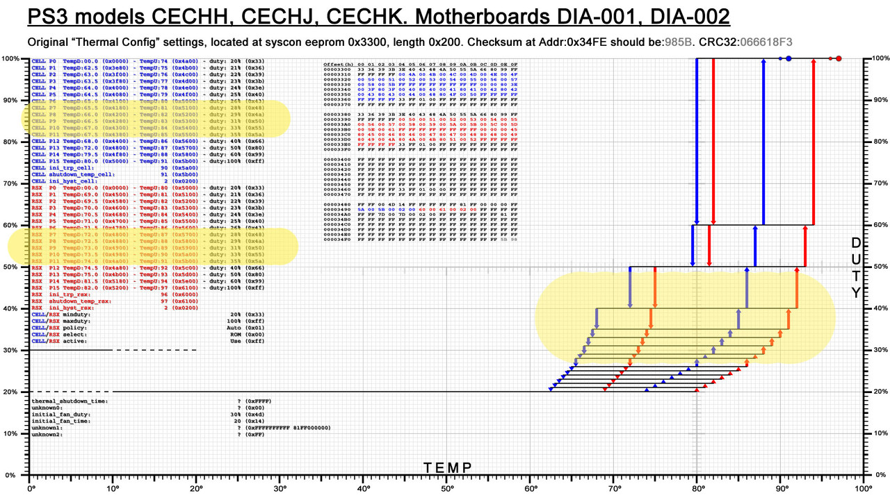
Lets use the DYN-001 for reference, keep an eye at this image while reading this post
The fan speeds are the "duty" values that appears in a list at left in black color (and also in the hexeditor view on that same image)
But... when we boot the PS3 the syscon uses a static fan speed (initial_fan_duty, usually with value 0x4D that represents 30% fan speed), and it keeps that speed for a few seconds (initial_fan_time)
After this few seconds the fan speed is reduced and we enter in the normal fan control (usually starting with 0x33 that represents 20% fan speed), that depends of the "fantables" (the areas colored in blue for CELL and red for RSX), DYN-001 uses this fan speeds:
So... we need to increase all that values (except the first 0x33 and the last 0xFF that represents 100% fan speed), but note this values are repeated twice for CELL and for RSX, is needed to change both and the speeds needs to match with each other
The location of the "thermal config" (a region inside the syscon EEPROM) depends of the syscon series (mullion or sherwood), the DYN-001 have a sherwood so is located at offset 0x250
What im going to post is from a syscon dump you shared some time ago and is the same that appears in this section in wiki, i guess the DYN-001 motherboard you have now is going to have the same exact data inside the "thermal config" region (this is not a strict rule though, we are not sure but you can check it by doing a dump)
The first thing inside the "thermal config" region is the "fantable" for CELL, it looks like this
You asked to start with 30% speed... but as i explained before the PS3 already is starting at 30% (and after some seconds the speed is reduced to 20%), so i suggest you to dont modify that initial boost that happens at beginning with speed 30%
This method modifyes the first speed (20%) into a value in between 20% and 30% (this way we preserve the initial boost)... lets say... im going to start with 25% speed
From now on is needed to take another look at the speeds in hex from factory (0x33 = 20%), and keep attention at how much units are added in each increment (6 units in the first "jump" and around 3 units in the next "jumps" up to the last two speeds where it does "jumps" of around 0x20 and 0x30)
Im going to calculate that same pattern, starting with fan speed 0x48
Now the real problem is... how to write all that values ? (14 bytes for CELL and another 14 bytes for RSX... and all the bytes are separated from each others)
There are 2 ways to read/write syscon EEPROM, the EEP command can deal with big amounts of data in a single "stream" (where all the bytes needs to be located consecutivelly), but in this case i think is easyer to use the commands "r" and "w" (to read and write a single byte), writing single bytes is better to prevent EEPROM wearing out because we are minimizing the amount of bytes we are writing
The only bad thing about doing it this way is that it requires to type a lot of commands, it will take 5 or 10 minutes, keeping attention at what you are typing... and eventually doing some "reads" to verify that what you wrote is fine, or doing a full dump of the EEPROM to compare with the original data in PC in a hexeditor, before and after the modifications
> r 255 1 (reads at offset 255 lenght 1, the result for DYN-001 should be 39)
> w 255 48 (writes the byte 48 at offset 255)
CELL
read at offset 255 lenght 1 (= 39 ?) ------> replace by 48
read at offset 25A lenght 1 (= 3B ?) ------> replace by 4C
read at offset 25F lenght 1 (= 3E ?) ------> replace by 50
read at offset 264 lenght 1 (= 40 ?) ------> replace by 54
read at offset 269 lenght 1 (= 43 ?) ------> replace by 58
read at offset 26E lenght 1 (= 45 ?) ------> replace by 5C
read at offset 273 lenght 1 (= 48 ?) ------> replace by 60
read at offset 278 lenght 1 (= 4A ?) ------> replace by 64
read at offset 27D lenght 1 (= 50 ?) ------> replace by 68
read at offset 282 lenght 1 (= 55 ?) ------> replace by 6C
read at offset 287 lenght 1 (= 5A ?) ------> replace by 70
read at offset 28C lenght 1 (= 66 ?) ------> replace by 74
read at offset 291 lenght 1 (= 80 ?) ------> replace by 90
read at offset 296 lenght 1 (= B3 ?) ------> replace by C0
RSX
read at offset 2C5 lenght 1 (= 39 ?) ------> replace by 48
read at offset 2CA lenght 1 (= 3B ?) ------> replace by 4C
read at offset 2CF lenght 1 (= 3E ?) ------> replace by 50
read at offset 2D4 lenght 1 (= 40 ?) ------> replace by 54
read at offset 2D9 lenght 1 (= 43 ?) ------> replace by 58
read at offset 2DE lenght 1 (= 45 ?) ------> replace by 5C
read at offset 2E3 lenght 1 (= 48 ?) ------> replace by 60
read at offset 2E8 lenght 1 (= 4A ?) ------> replace by 64
read at offset 2ED lenght 1 (= 50 ?) ------> replace by 68
read at offset 2F2 lenght 1 (= 55 ?) ------> replace by 6C
read at offset 2F7 lenght 1 (= 5A ?) ------> replace by 70
read at offset 2FC lenght 1 (= 66 ?) ------> replace by 74
read at offset 301 lenght 1 (= 80 ?) ------> replace by 90
read at offset 306 lenght 1 (= B3 ?) ------> replace by C0
*Im suggesting to do a "read" before "writing" every byte as a safety check but the "read" commands are not really required, are just incase
*And remember... atfter writing the new data you need to fix the checksums by doing the "eepcsum" command and writing the value at offset 0x7FE
*Also... before doing all this make a syscon dump to keep it as a backup just incase you made some mistake when writing in syscon EEPROM (or incase i made a mistake when writing this post)
@sandungas did you ever get a chance to make thermal graphs for the models @vyktormvmpay25 uploaded in this post?
I just added the fan curve pics you did on page 1 to the YLOD post I made earlier (also the JTP-001 from here), but the other models would be good to link as well. I don't have the time to make the graphs with another project I'm working on and wanted to check if you uploaded them somewhere else. Perhaps the devwiki?
Not yet sorry, but at some point i will make them and i will upload them to wiki, at the right of Syscon Thermal Config page
The "problem" i had is im very picky sometimes with the details, i have all the images separated in tenths of layers in the same photoshop PSD file (current version 23), this way i can continue improving all them
Everytime i was doing something different with a new image i was stepping back to modify the others (aligning texts, etc...)
One of the last things i did was the graph for DEB-001 motherboard (DECR-1400 PS3 model) where i changed the background color to black, after that i made JTP with a black background too... but i have not modifyed the colors of the others yet :/
Around the same dates is when vyktor shared all that syscon dumps from the superslims that was awesome and increased my list of "things to do" a lot, lol... also as far i remember there is something in the superslim thermal configs that requires to modify all the others (a weird alignment or something like that, dont remember well... i need to dedicate some time to see how to solve that problem)
The point is... if you download all the images to the same PC folder and you start displaying them like an slideshow it helps a lot to see what they was changing in every revision, i like that "feature" a lot and the only way to achieve it is if all the images are perfectly aligned with each others
But yeah, i have to complete the collection of images at some point
Yeah, I just compared the COK-00X to the SEM-001 profiles to see how they lowered the RSX thermal ramp up temps. G models have the same CPU/GPU, and SONY did not include them in the extended warranty for repairs. Evidently SONY thought they addressed the issue adequately. It's a telling fact that they saw the need ramp up fan speeds at much lower temps, not to let it get so hot before ramping up. They finally saw the need to prioritize temps over sound after being woken up over the YLOD.
The fan curve is a mitigation attempt and admission of guilt.
EDIT: Nevermind, G models have 65nm CPU. I was wrong.
Also, the G models used the 15-blade G14T (according to wiki). The 15-blade D14F has tested better than the 19 blade BG1402 in A-E models. These fans are all interchangeable. In other words, we could consider the SEM-001 fan and fan tables as SONY's official "YLOD reducing" 90nm RSX/CPU FAN curve.
Edit: No I'm an idiot! G models have a 65nm CPU. Forget everything!
Yeah, I just compared the COK-00X to the SEM-001 profiles to see how they lowered the RSX thermal ramp up temps. G models have the same CPU/GPU, and SONY did not include them in the extended warranty for repairs. Evidently SONY thought they addressed the issue adequately. It's a telling fact that they saw the need ramp up fan speeds at much lower temps, not to let it get so hot before ramping up. They finally saw the need to prioritize temps over sound after being woken up over the YLOD.
The fan curve is a mitigation attempt and admission of guilt.
Hmmm, yes, there are many differences in between the thermal configs of the first PS3 models, but one of the most important are the speeds
Let me explain this in a simple way, what im going to say applyes to all the PS3 models, but probably to PS4 and PS5 too... if we think in the thermal config settings as a sequence of speeds that increments, the last speed is always configured to 100%... i use to call it one of the "def con" speeds
But the fact is the two previous speeds can be considered "def con" speeds too
If you take a look at the graphs you are going to notice this 3 speeds are always separated from the others (there is a noticeable gap before them)... lets say... they are assigning most of the speeds to the range of normal working temperatures and the other 3 speeds are "def con 2", "def con 1", and "defcon 0", lol
Sony doesnt really wants any of his PS3 to use the "def con" speeds (because uses high values so are noisy)... if for some reason the PS3 uses them it means there is a thermal problem with it
The first PS3 models was reaching that "def con" speeds too easilly.... so in CECHG they increased one of the "def con" speeds from 50% to 55%... i guess the purpose was to prevent the PS3 to use the next "def con" speed (at 75%)
To me looks a dirty fix, the best they could do was to move around all the other speeds to cover a wider range of normal workload (inside a game, without hardware problems)
Look at the graph of the CECHG, most of the initial speeds are "wasted" because are too much close to each others
In DIA motherboards they redesigned the thermal config very well, and they reduced 2 of the "def con" speeds (probably they was more confident that the PS3 was not going to use them under normal workload)
Is tricky to explain it with words, i made a dirty drawing with the DIA-001 to show you what i mean
The thermal config is designed to keep the PS3 working under an optimal range that i sprayed in yellow, this is why most of the speeds are inside that range (lets say, they are fine-tunning that range to achieve smooth speed transitions to reduce noise annoyances). The only speeds out of that range are:
-The 3 "def con" speeds at top (your PS3 is not supposed to use them)
-The speeds at beginning that are really a "warm up" and are a waste of resources (but achieves smooth speed transitions to reduce noise annoyances)
If you ask me how to configure this, i would say to keep the 3 "def con" speeds... but dont dedicate so much speeds to the low temperatures because we dont care... then dedicate all the remaining speeds to the range of working temperatures i sprayed in yellow... but extend it a lot more
Lets say... in this config for DIA-001 the speed increments 1% every single 1ºC... thats paranoid, they are wasting all the goodies in a small range instead of covering a wider range
Lets say... they was very optimistic into thinking that the PS3 was going to stay in that range for many years... in the practise you know the story is very different, when the temperatures goes over the range the settings are not good enought and you are pushed into one of the "def con" speeds too much easilly
These keep the fan from changing its percentage all the time. That's annoying when you're trying to watch a movie and the fan percentage keeps ramping up/down dynamically (like how webMAN mod works). So it only changes when above a certain temp, and won't drop back to the lower fan percentage until the temps fall below a point much lower than high temp that just triggered the fan increase.
It's like a wide hysteresis. Actually you could represent it that way.
Fan %
Setpoint (°C)
Hysteresis(°C)
20
20.0
±
40.0
21
72.0
±
6.0
22
72.6
±
6.3
23
73.3
±
6.5
24
73.9
±
6.8
25
74.5
±
7.0
26
75.1
±
7.3
28
75.8
±
7.5
29
76.4
±
7.8
31
77.0
±
8.0
33
77.6
±
8.3
35
78.3
±
8.5
40
78.9
±
8.8
50
79.5
±
9.0
60
84.6
±
6.3
100
85.8
±
7.5
The hysteresis is |ΔT| / 2 and the setpoint would be T1+Hysteresis. So if the fan spins at 23% between 70-83 degrees, the Hysteresis is |70-83| / 2 = |-13| / 2 = 13/2 = 6.5C. The setpoint = 70C + 6.5C = 76.5C. In other words the Fan will stay at 23% if the temps are 76.5C +/- 6.5C.
I actually prefer to represent the fan curves this way. We're used to seeing curves with a single set-point represented. The Hysteresis is interesting only because it shows they widen it as temps increase, meaning they want it to stay at that fan step longer before changing again. Keeps the changes from becoming annoying.
But i wanted to represent all the values, by simplifying them is not posible to see the weirdness they did in some PS3 models, like the SEM-001 motherboard where the values of "tempU" are sensitive enought (the fan increases speeds normally), but are nerfed for "tempD" (the fan only reduces speeds after a huge temperature reduction)
The resulting curves to speedup are fine, but the curves to speed down are weird, the only way to show this is to display the 4 curves
Edit: actually, this graph have 6 curves to complicate it a bit more, lol
Btw, there is a setting for the hysteresis, every thermal sensor have his one, named "ini_hyst_cell", "ini_hyst_rsx", and "ini_hyst_sb" (incorrectly labeled as "bevr" in the graphs i made for COK-001 and SEM-001), this value is always 0x2 in all PS3 models, and i guess it represents 2ºC
But im still trying to figure which rol plays the "hyst" settings in all this thermal configs... i mean... im not sure if the "hyst" value is applyed for every "tempU" and "tempD"... or just for the other temperature settings related with thermal shutdowns... or whatever
Is tricky to know it, i guess the best way would be by giving them value 0x0 (so no hysteresis) and see how sensitive it becomes... then give them a high value and see if the sensitivity was reduced
The hysteresis value set in syscon just affects how sensitive the thermocouple reading is.
I became familiar with the term hysteresis working on aquariums. Thermocouples have some level of inaccuracy in the reading and will jump around a bunch. If you set the hysteresis too low, the controller will oscillate between on/off like craze. That can burn out you heater, fans, or whatever is being switched on/off. This is the function of a PID controller BTW, it just does it using calculus (yuk!). So setting a higher hysteresis means the temp has to increase/decrease more before the controller recognizes the change and switches the device on/off.
The syscon's hysteresis is a fail safe. Before it'll turn the fan up a step the therocouple reading must crawl above the setpoint value + the hysteresis value. And it wont step down again until it crawls below the setpoint - hysteresis. It gives a small buffer to prevent oscillating between steps like crazy.
That won't happen if the min/max of the fan curves them selves are set wide enough and overlap with eachother. But if you set them too close, the hysteresis fail safe in the SYSCON will prevent craziness.
It makes sense to use the hysteresis value to reduce the sensitivity, in the practise we can think in it as a time delay because everytime the temperature values triggers a new speed the change is delayed a bit
The weird thing is if we try to imagine what would happen if we apply a hysteresis of 2ºC to all the "tempD" and "tempU" values in some thermal configs like this one:
As i was mentioning before, this config have a range where the speed increments 1% every 1ºC... but if we sum the ±2ºC hysteresis there is going to be a lot of overlappings
Talking in numbers... in this thermal config, the first time RSX triggers a new fan speed happens at 80ºC, right ?. And next speeds at 81ºC, 82ºC, 83ºC and so on... (+1ºC each increment)
Well... if we sum a +2ºC to that values of "tempU" we are overlapping the next setting (80+2 would push us into the third fan speed)
This is one of the details that makes me doubt if the hysteresis value needs to be added to all the temperature values, tempU, tempD, and also the thermal shutdown temperatures, and some other temperature values (all the temperature values with 2 bytes lenghts)
Maybe the syscon firmware is designed to use the hysteresis value in some of the temperature values, but dont use it in others
-----------------------
I was thinking about adding curves on top of my graphs to do it a bit more noob-friendly but this decission didnt convinved me much, because a curve would represent a gradual speed increment
Lets say, a gradual speed increment would be if the speed is at 30% and we change it to 35% the fan would increase the speeds gradually from 30--->31--->32--->33--->34--->35, but this is not how it works
The speed changes happens instantly, lets say... is a violent change from 30 to 35... so is more accurate to represent it with straight lines instead of curves
Lets say... the curves would look better visually but are a bit misleading, im not completly against them though, im still considering adding them to my graphs but im not sure how is the best way to do it
One of the reasons why im not sure how to do it is because the hysteresis values are indirectly involved in the way how we represent this curves
I was also thinking in representing the hysteresis in my graphs by increasing he width of the vertical arrows... but a hysteresys of ±2 would mean to give the vertical arrows a width of 4ºC... is a lot visually
If you want to represent them with curves is better to represent the curve for "tempU" separated from "tempD", or just ignore the values for "tempD", but dont merge them
In this image you are merging them and it looks like the CELL (blue line) increments the fan speed for first time around 62ºC
But the fact is CELL increments the fan speed for first time at 76ºC
For someone that looks at your image thinking the "dots" represents the accurate values is very misleading because you have a huge deviation from the real values (in this example a deviation of 14ºC)
The reason of that deviation is because you are merging "tempU" with "tempD".... and the "tempD" is "pushing" all the control dots a lot to the left
Btw @M4j0r can you review the RE notes you have about the hysteresis values ? (ini_hyst_cell, ini_hyst_rsx, ini_hyst_sb)
Every small hint, detail and even your speculations could help a lot to help us understand how it works and what we can do to represent it visually. I would really like to represent it in my graphs
what RIP-Felix is suggesting makes lot of sense though... in theory the hysteresis is a value that belongs to the thermal sensor... so all the temepratures sent by the thermal sensor should be affected by it
But probably the thermal monitor have his own hysteresis (the config iside the thermal monitor chip)
And as mentioned in my previous post if we consider the hysteresis is applyed for every "tempU" and "tempD" the results in the practise are weird because are overlapping each others (it would be a pita for the person that was configuring the thermal config)... right now i think thats not the correct way
Im wondering what means the prefix "ini" from the names...ini_hyst_cell, ini_hyst_rsx, ini_hyst_sb
It means an initial condition ? (only used in the first seconds when the PS3 boots ?)
the point of my graph is just to represent the curve in a easy way. I see your point though.
another way to think about it is as the PS3 having 2 fan curves. 1 for ramping up and another for ramping down. it wont ramp down until the temp intersects the ramp down curve.
Its probably better to just graph the high temp, to be more accurate to the way people think about fan curves. But you could graph both (high in red, low in blue). But i just graphed the midpoint and ignored the hysteresis for the sake of comparison. Just to make it easier to compare.


 and is the same that appears in