PS3 WiFi/BT Board Error 8002F1F9 (Update Loop) - Diagnostics/Reports/Repair

VTSTech

Developer
d02e11e963a179ff6e62b2b5ebd19b51.jpg


Been working on this one for a bit with a CECH-3001B. The shotgun fix would be to just replace the entire sub-board. This would most likely repair the error unless it is another related motherboard component that connects to the subboard.

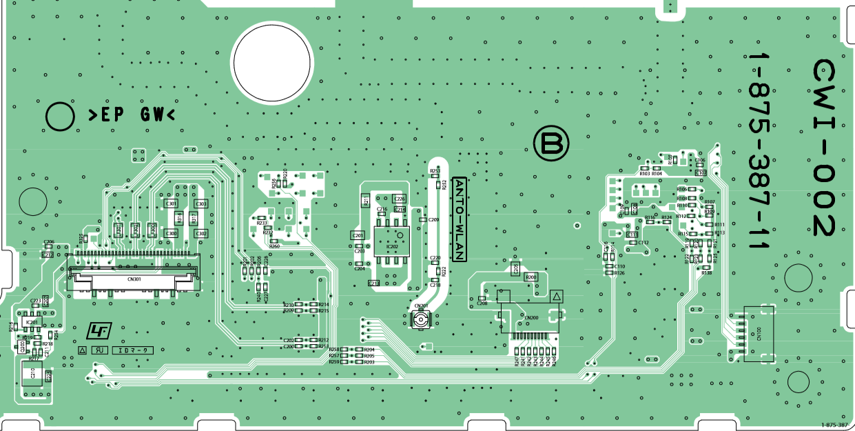
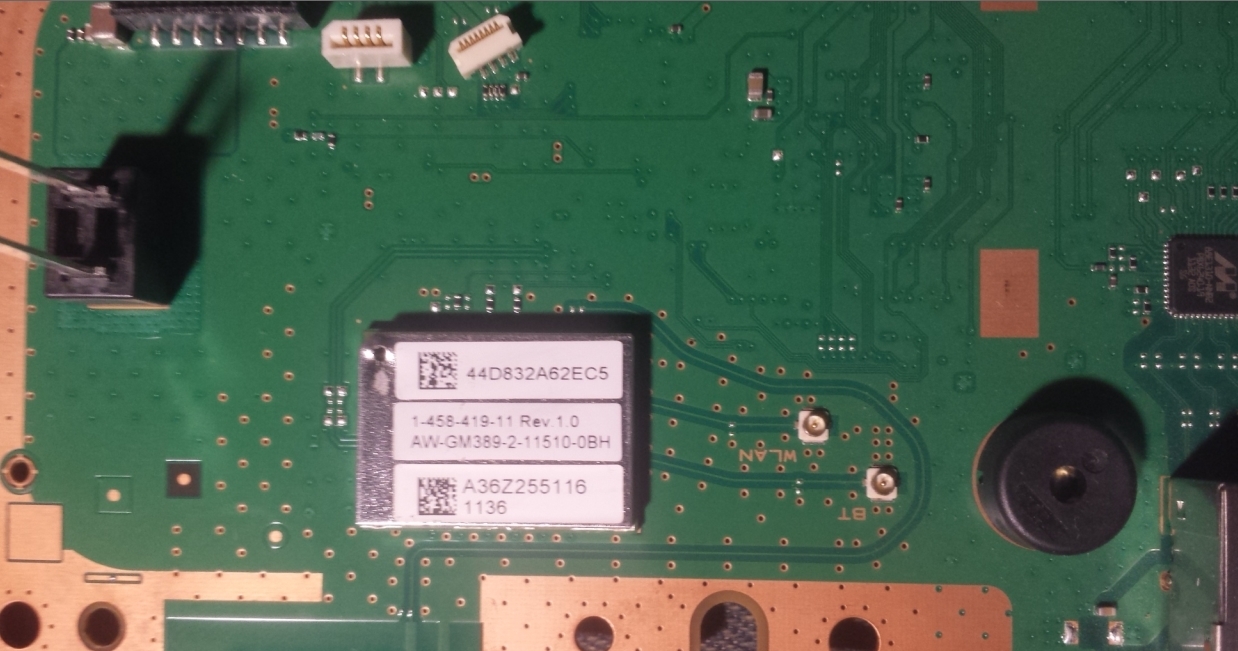
This is the subboard (KTE-001):

7387c4fa708270ce90aaab5372e75b26.png

17dd187acd319d26877d6ec1ef75e7ef.png


99f886dfbd7b96858d4fa319b11cde85.jpg


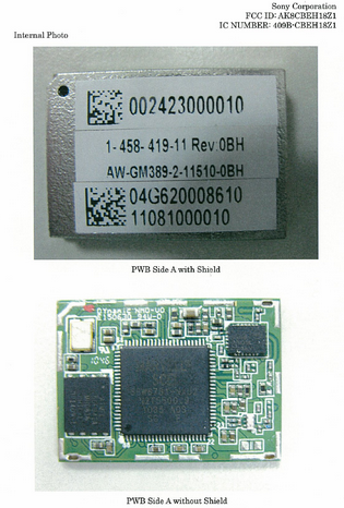
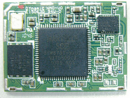
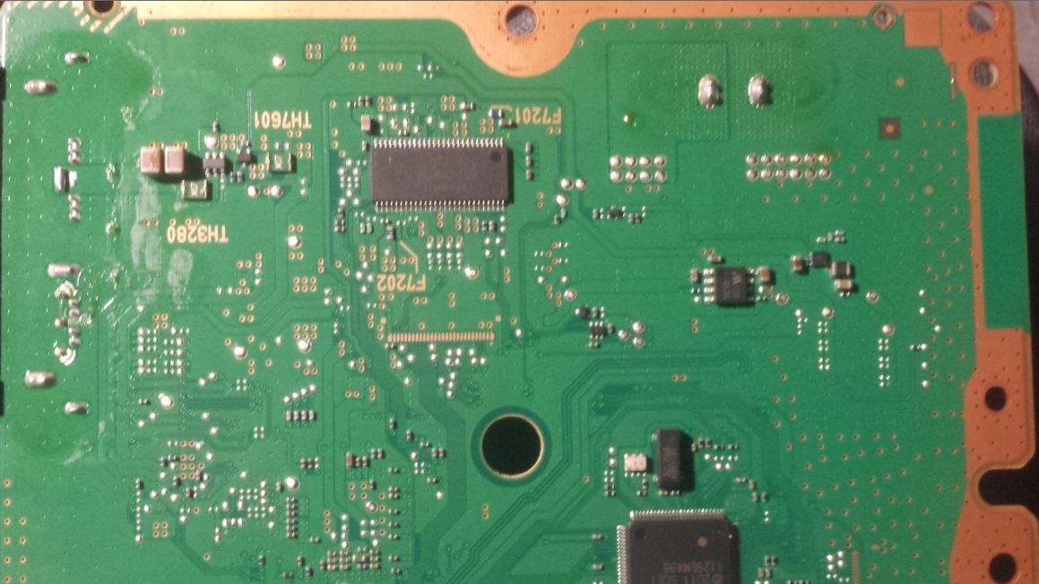
Reverse side (KTE-001):

3b8bbe90ebff88d393a96fde89bbb4e1.jpg


I've read that "pulling the HDD during the update for a few seconds" can allow the update to progress past the error. I'm still investigating this, There is two confirmed reports of people succeeding with this however.

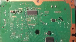
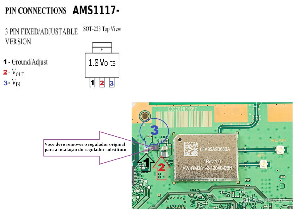
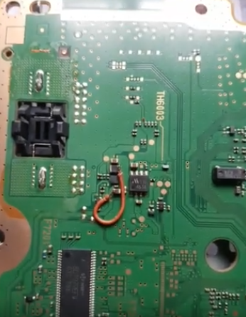
I've also read/seen that bridging two components together on the motherboard can revive the subboard, Here is an example of that (not mine), This is from a CECH-25XX

UqKxnd7.jpg

--
Here is another (not mine) example of a bridge fix. (JSD-001)

3d2ad7efb6b2a6f822a5cafa33f816ce.png


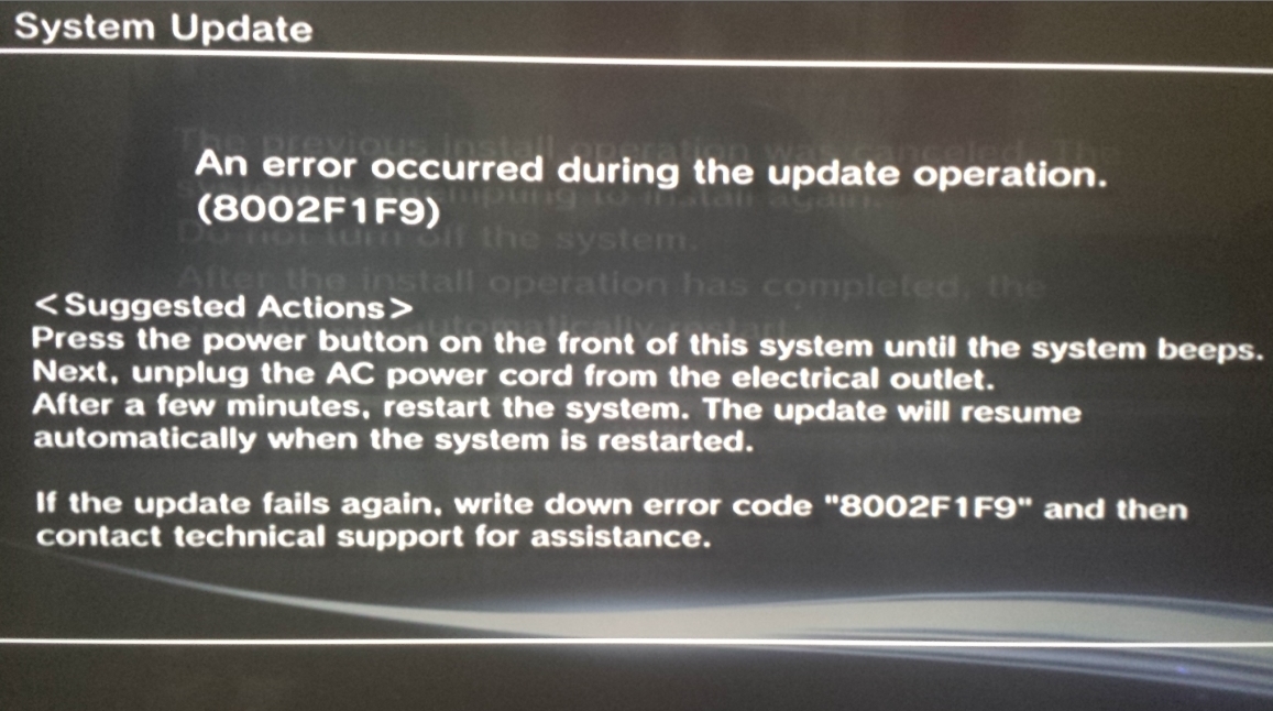
CECH-3001B - I did manage to get this thing into Recovery Mode once to feed it a new update PUP. So it's likely trying to install HFW 484 or 485 (formatted hdd again gives recovery boot, def using 4.85.1 hfw)

38% not pulling HDD at all. pulling at 34% errors at 44%, pulling at 43% errors at 52% ....

New behavior Pulling at 31% 8002F107 (Verification Failure)

pull at 48% error at 58% 8002F1F9
pull at 28% error at 46% 8002F1F9
pull at 27% error at 51% 8002F1F9

around 30-34% there is a series of quick reads, only time HDD light 'blinks' in rhythm really. These appear to be hash checks (or it could be 2x Read/Write pair. Is 4 distinct blinks) pulling at this time causes verification error...
--
hdd light on im assuming reading/writing to hdd, light off im assuming reading/writing to flash. Been pulling while light is off for about 3-4 sec. Maybe to screw this up in our favor need to pull while light is on. (Pretty sure it just reattempts the current read/write seq at that point)
--
pull at 29% w\ light on. 8002F107
pull at 33% w\ light on. 8002F1F9
--
The next time the HDD Led lights up after the rhythmic blinks is when the 8002F1F9 error happens.

Pulling during those blinks, gives long hdd led on reinsert (init/detect?) and then the sequence you interrupted repeats. then 8002F1F9 on next hdd led

HDD can only be removed for about 4 seconds before progress halts usually

Time from power button pushed/beep to install failure is 2m55s...
--
Once I get a new battery for my multimeter I'll test the trace connected components see if i can find anything obviously not working. Haven't got the heatshield off the module yet -- eventually failing all else i will likely take the whole thing off and put on another.

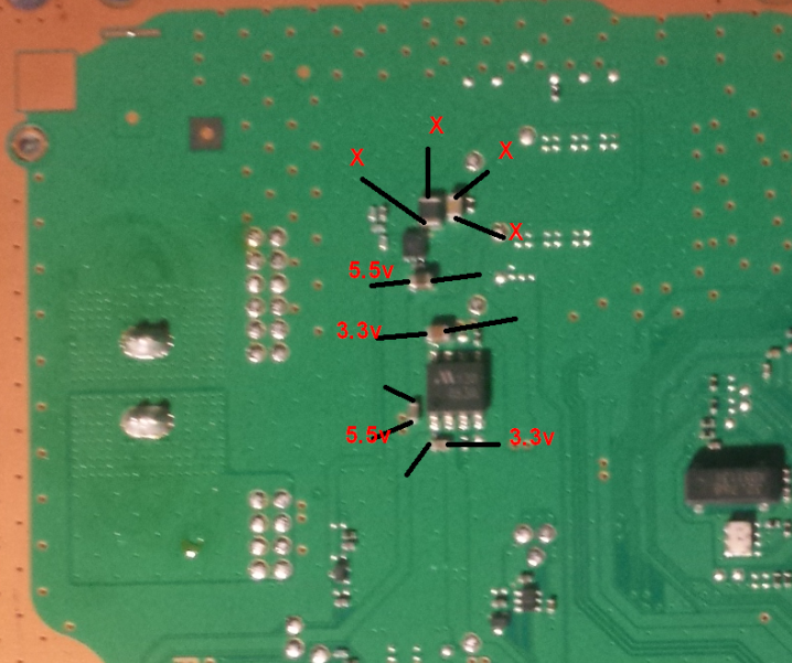
These are directly under the subboard (KTE-001).

Resistance

41f7e4675c789785f0febe27909c368f.png


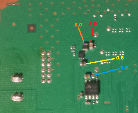
Voltage (2 seem dead)

 
Last edited:
You should desolder the metal shield of the BT/wifi module, it can be seen in this photo, is soldered in the corners or/and all along the borders
99f886dfbd7b96858d4fa319b11cde85.jpg


If i remember right, nside it there is a chip, a crystal, and a few resistors and capacitors
The chips cant be checked i guess because probably there is no pinout/datasheet of them, also probably are failproof
My bet is 90% of the problems are caused by one of the tiny capacitors or resistors
 
Last edited:
What I read from the underside looks ok to me, consistent readings. So a bridge likely wouldn't help. (reading for voltage are different, bridge may still help..)

I've seen pics with the shield off (added to op) there's a ton of resistors/capacitors in there. I doubt I'd be able to bridge anything in there...too confined/small
 
Last edited:
My thinking right now is to find out *why* those bridge fixes work (sources are not english)

And possibly to compare readings from a working 3XXX (if anyone had those handy? if not I could always open my own working 3XXX)
 
My thinking right now is to find out *why* those bridge fixes work (sources are not english)
Probably the big chip have several pins for V_IN, also the other components could have more V_IN, and everyone of them should have an small capacitor located the most closer posible to the component

That lines for power are not connected together in the wifi/BT board... they goes separatedly to the BGA solder balls at bottom
So i guess the people fixing it with bridge wires are connecting the different V_IN's to each others
 
The two capacitors on the top, with x's are grounded on both sides...

Tried bridging the 5.5v to the bottom of the bigger one on the left, didn't work. (No Boot/No Lights)

Tried bridging the 3.3v to the top of the bigger one of the left. (No Boot/Red Light/Green Light/Off)

Seen a guy use a 1.8v regulator and send the 5.5v thru it with another ground. Don't see what side he goes into, but it's one of the top ones...Seems like they might expect/take 1.8v

Undo it all and it's back to booting, same behavior. 8002F1F9 @ 38%
--
So now my thinking is the problem is likely with those two shorted capacitors. They sit directly under the subboard. Could be a short inside the board. Once I get it off I'll be able to tell if the short persists. If it does. Then its the capacitors themselves. Replacing them might fix...If it doesn't still ground both sides. Then short is in subboard. Will probably just replace at that point.
 
Last edited:
In the firmwares pup file comes a file BLUETOOTH_FIRMWARE.pkg I guess it is the driver and until it is installed the process cannot be completed, the question is what is preventing this, it is unforgivable what s @ ny did leave a console unused because the bluetooh and the wifi do not work taking into account that you have the usb and lan ports, this week a guy from my fb group asked if it was normal for the wifi and bluetooh to fail, unfortunately I saw 10 hours late its publication when I wanted to warn you not to update the firmware the naive had already done so in the hope of fixing the bug.
 
At least 3 of those capacitors are dead on the bottom side, possibly 1 on top side too. No luck getting them off with a soldering iron. Will try tmrw with a heat gun.

Figured it would be easier to get a capacitor off than the entire wifi/bt board. Doesn't seem like any of it is coming off easy.

I noticed the BT_FIRMWARE PKG in an extracted PUP as well, Only like 600kb -- That would read/write in an instant

This isn't my "main PS3" that is broken, I bought this system broken specifically with this error in hopes of fixing it.
 
Most cases for 25xx and 3xxx series caused by dead capacitor below the board

I think that is a voltage regulator you have highlighted. I've seen a guy bypass that part using a 5.5 to 1.8v regulator from one of the nearby capacitors

Tried reading the text off that guy with a microscope, iirc it was 'J7V'

87f9b6da73dd0575a31b1f5dec7ed4fc.png
 
Last edited:
I was in a similar situation a few hours ago. A friend gave a 4211C that was dead (not even standby red light), then I checked the psu and it was ok. The other thing it's almost always causing this for no reason is the BT/Wifi module that gets damage. You can test if this is really the problem by removing that voltage regulator and test the module. If some capacitors are in short, then you'll have to change the module, which is a pain in the ass. If you're lucky, you'll only have to replace that regulator by a 1117 (1.8v).

My solution was removing the regulator, the PS3 turns on, but there's no wireless signal, and you can't update either, because it will give you the error that you have.
 
So one of these guys, I was thinking about doing this, dunno if i wanna buy 100 of them thou. was hoping i could find one lying around...

I do have a GLoD (CECH-2XXX) that I can use a donor ... maybe I could swap the regulator from that. see what happens. (The WiFi/BT module on 2xxx doesn't look same as 3xxx, don't think i can just swap those)

My current thinking was to take off some of the caps coming back as short (X's on pic all coming back as ground), test if they still short when removed, if they are, swap them out for some caps from the GLoD.

0-1506-400x400.jpg


https://rarecomponents.com/store/AMS1117-3.3V-Voltage Regulator-SOT-223-Pack of 20
 
Last edited:
Generally capacitors goes in short because something on the board gets damaged, i.e an IC. They got damaged, there's no lie about it, but with time and poor work enviroment, so most likely the IC on my board is dead, and maybe the one you have too. So you need to check those caps. In that case changing the regulator won't do nothing, as the problem is not there. I will still buy a pair of 1117 to see if I can repair the module, because I don't have another one to replace it. Also, you need a solder station with heat gun, like those chinese ones, to remove the regulator and the module, but I think you already know this.

I recommend you first to eliminate the short of the module, then try to change the regulator or replace it with a 1117. I'm gonna do that.

P/S: Just in case.

modulo-wifi-bluetooth-ps3-super-slim-rebalada-D_NQ_NP_764699-MLB26316565407_112017-F.jpg
 
I do have a heat gun, I just don't have an actual wifi/bt module to replace it with. I'll get one eventually. Haven't determined the source of the short yet. The module may not even be the cause.
 
101471719_2983587678399906_5887383045840830464_n.jpg


here is a more closer look, according to the previous photo those are the connection point, as I understand the chip is a Mitsumi 463A voltage regulator, and that pin number 8 is a 3.3v_standby_rail_1 ,
 
101471719_2983587678399906_5887383045840830464_n.jpg


here is a more closer look, according to the previous photo those are the connection point, as I understand the chip is a Mitsumi 463A voltage regulator, and that pin number 8 is a 3.3v_standby_rail_1 ,
Chip 463A is feeded directly with 5v standby from the PSU, this means is always active, and converts the 5v input voltage to 2 rails of 3.3v each

Are you sure the wire is soldered to that chip ?, i cant see it in the photos
Anyway, i guess that trick with the wire is intended to feed the wifi/BT module directly (bypasing some other components) but this could only work incase your problem is the same, located in that other components

The fact is there are a lot other posible culprits for a wifi/BT module failure, as i mentioned in this other thread there are a bunch of resistors and capacitors inside it (only visibles after desoldering the metal shield of some wifi/BT modules), this tiny components are prone to failure because the wifi/BT module works with a bit of overheat
https://www.psx-place.com/threads/s...-error-8002f1f9-help.23236/page-3#post-244530
My guess is the big 3 "chips" inside the wifi/BT module are pretty much failproof and can work fine under an small overheat so most probably are not going to be the cause of the problem... i mean... ever
This sucks because we know that 3 chips are the most important and most probably are working fine
 
@sandungas to the looks of it via the pic that @VTSTech posted, it looks like that the wire is soldered to pin number 8 of Chip 463A... one of my ps3 slim is having the 8002f1f9 issue and I am looking to perform that bridge fix, I'll try to reformat the hdd then use the HFW firmware to update, if all else fails I'll resort to the bridge fix
 
Back
Top