sandungas
Developer
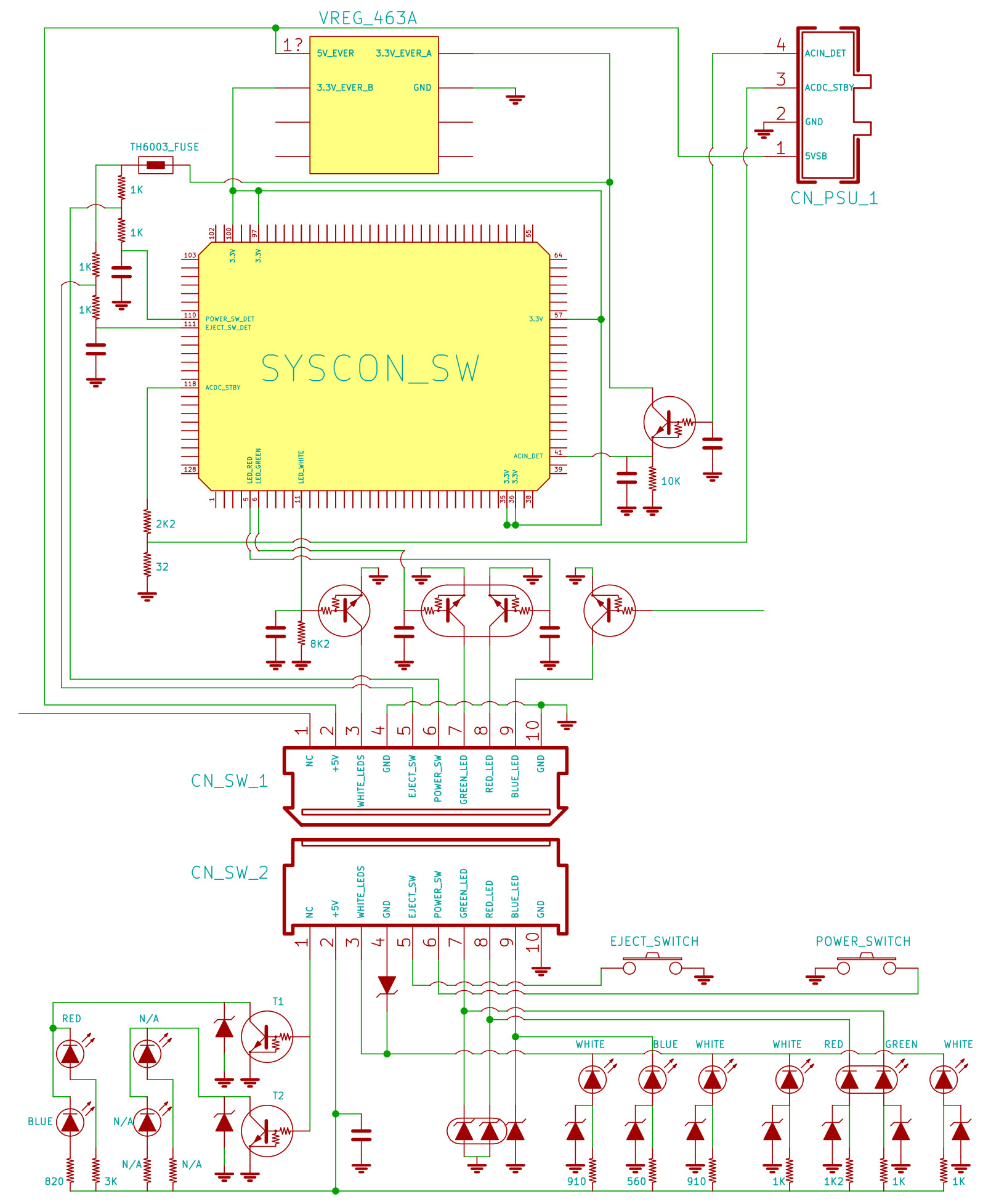
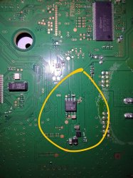
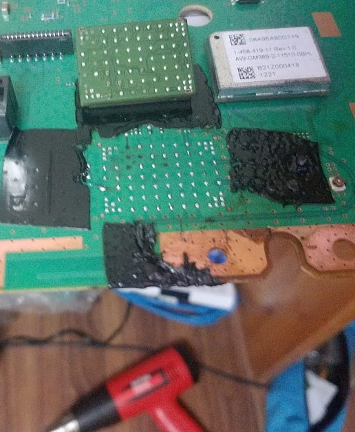
After a better inspection of the images i can confirm the chip is actually a Mitsumi 463A voltage regulator, and the wire is bridging pin#1 (5V_EVER) with pin#8 (3.3V_EVER_A)@sandungas to the looks of it via the pic that @VTSTech posted, it looks like that the wire is soldered to pin number 8 of Chip 463A... one of my ps3 slim is having the 8002f1f9 issue and I am looking to perform that bridge fix, I'll try to reformat the hdd then use the HFW firmware to update, if all else fails I'll resort to the bridge fix
In other words, it connects votage IN with voltage OUT (rail 1)
https://www.psdevwiki.com/ps3/Talk:Regulators
https://www.psdevwiki.com/ps3/File:Mitsumi_463A.jpg
https://www.psdevwiki.com/ps3/File:SYSCON_SWx_JTP-001_JSD-001_HSW-001_CN101.jpg
In few words, i think is a bad idea and could be dangerous, as you can see in the third link that rails are connected to other components (and we dont know how many more components are connected to that rails). In the original design that rails have 3.3v but when you solder the wire to 5v all that components are going to be feeded with 5v
Anway, the first thing you need to do is to meassure the voltage with a multimeter in pin#1 and pin#8 of mitsumi 463A chip
If the multimeter says there is 5v in pin#1 and 3.3v in pin#8 then the chip is working fine and there is no reason to solder the wire