I made a drawing to show you what i meant, is easy to do, and is safe as far we dont abuse of it
The "spring" effect i mentioned happens because the clamp is like an V (is not flat), when we assemble the heatsink with the bolts thighten we are flattening the clamp, but the clamp is flexible and is trying to recover his V shape.. so is like the clamp is "pushing" at its center
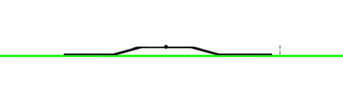
To meassure that bending is needed to place the clamp on top of a flat surface (on top of a table)... represented with a green line in this image
Note the clamp have an small "bump" at the center, all the force is concentrated in that small point... so we need to meassure the location of that point using the table surface as a reference
If you place it like this you need to meassure at the center
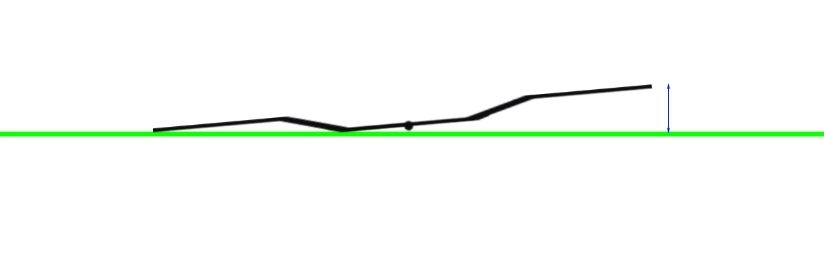
And the other way to meassure it is this way, inverted, pushing one of the sides of the clamp down... and messuring the height at the other side. This is easyer to do, and is more accurate because the distance is bigger
Also, note both clamps are simmetrical (left to right sides of the clamp) and identical... so you can take both clamps and place one on top of the other to compare the bendings and to adjust them equally
*And remember... before doing any custom bending the best thing you can do is to meassure the original bending from factory, and take note about it somewhere... just incase you decide to do other corrections to the custom bendings back and forth
If you repeat the same process many times without taking any note there is going to be a point where you are not sure if you are abusing of that bending too much
My suggestion is to just increase the bending a few milimeters