many thanks for the thorough explanation, will need to read it few times and hopefully i will understand.Ok, the circuit in this mdoel is easyer (because is single layer, so everything is in one side of the board), also there is a high quality photo in psdevwiki where it can be seen the whole circuit
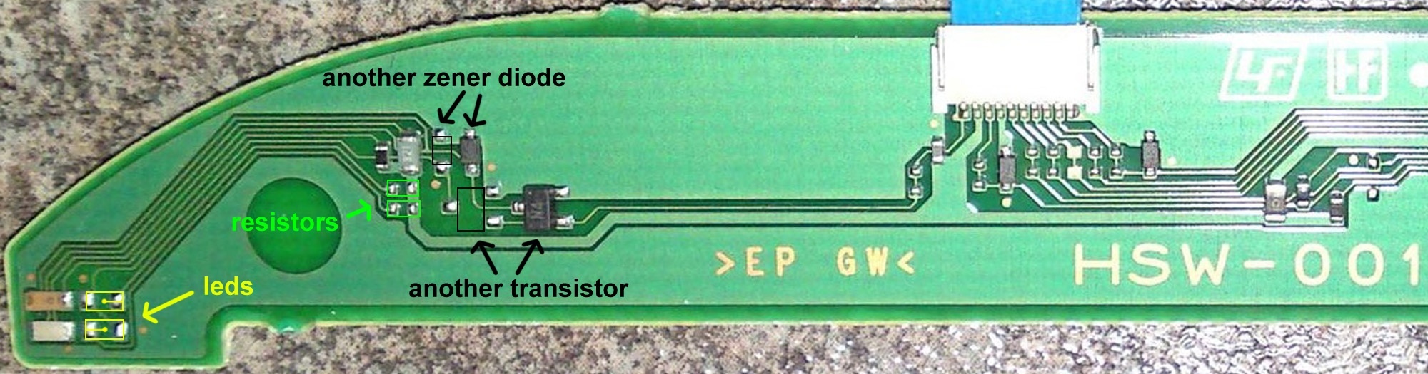
The probem in this board is it have only 2 leds at the corner (1 red and 1 blue), but are "driven" together by the same transistor
I think i mentioned it before, but i will try to explain it again, all the leds of the board (except the eject led) are "controlled" by transistors. The led have his + (positive) pole soldered permanently to a big 5v rail, and his - (negative) soldered to the transistor
In theory... syscon should send a control signal to the transistor, and the transistor is the responsible of "closing" the subcirtuit of the led (by connecting the - pole of the led to ground)
In plain words... we are enabling the leds by connecting his - (negative) pole to ground... and we use to do it by soldering a wire to the transistor pin (or his nearby alternative solder points, or in the connector)
This is the basis, what can be seen in this photo, im joining together the - poles of the 2 leds in the corner... with the - (negative) poles of the white leds (there are 4 white leds btw, all them connected together)

The result is the 2 leds of the corner (1 red and 1 blue) are driven together with the 4 white leds
The problem to chieve what you want to do is you need to remove one of the leds and solder it in the other traces at his right
Think in them as a total of 4 leds... but connected in 2 groups of 2 leds each
-Group A have 1 red and 1 blue
-Group B have 0 leds
You are using an out of date browser. It may not display this or other websites correctly.
You should upgrade or use an alternative browser.
You should upgrade or use an alternative browser.
PS3 How to Enable Hidden Blue/Red Light in PS3 SLIM
- Thread starter LuanTeles
- Start date
sandungas
Developer
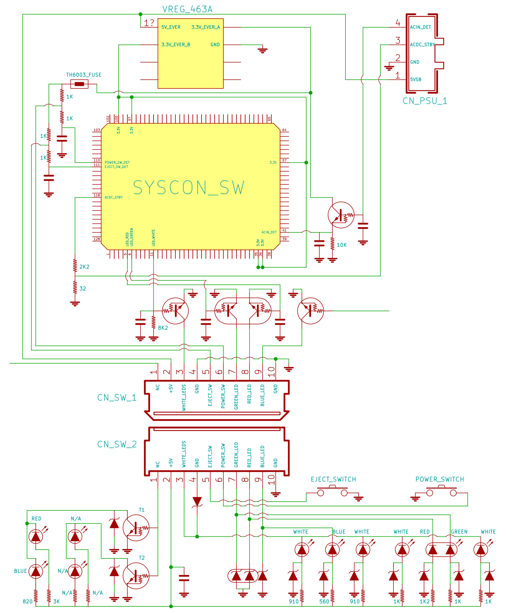
I made an image to show you how many different ways there are to do this mod in HSW-001

The dots at the connector follows the real colors:
Red and green are used by the power button
Blue is for the eject button (controlled by the BD drive btw, not syscon like all the others)
And the white leds are located at the back of the power and eject buttons (2 white leds for each button)
The dots at left are the "collector" pin/s of the transistor/s
The yellow dot is controlling the group of leds at the corner composed by 1 red and 1 blue together (note the - traces are joined together)
And the other purple dot... well... is not controlling anything because there are no leds from factory in that group
Just to have a better understanding of the circuit... is designed to do this:
We dont need the transistor neither the diodes... but to have 2 different colors and 2 different "states" you need to add the resistors and the leds
This is the full circuit of HSW-001 btw (and some moterboard components where can be seen more transistors responsibles of the leds control)
Last edited:
I would like to say thanks to this thread.
I got mine partially working only because I destroyed the Blue LED.
So I ordered new LED's from the one @sandungas recommended: SMD 0805
I was following the tutorial from the attached image from @justanyone

I got mine partially working only because I destroyed the Blue LED.
So I ordered new LED's from the one @sandungas recommended: SMD 0805
I was following the tutorial from the attached image from @justanyone
sandungas
Developer
Dont feel bad for burning LEDs with the solder iron, uses to happenI got mine partially working only because I destroyed the Blue LED.

https://imgur.com/a/HUJI01Z
I tried it on my ps3 the other night and did some slight changes to how Griggs had done it. I ran two wires from the transistors to SW- and NW- then a made two small wire jumpers to the vias between SE- , SW- and then NW- and NE-. I also added a 1.5k resistor to the SE+. This seems to have worked better than expected for me and nothing blew up.. yet.
I tried it on my ps3 the other night and did some slight changes to how Griggs had done it. I ran two wires from the transistors to SW- and NW- then a made two small wire jumpers to the vias between SE- , SW- and then NW- and NE-. I also added a 1.5k resistor to the SE+. This seems to have worked better than expected for me and nothing blew up.. yet.
Hi.
I know it's a bit old thread but quite interesting one to.( i read all posts and like to thnx anyone who participated for handy information, i find out my 2004B PS3 has DSW-001 which i can have 2 different colors with 2 different stages)
But i would like to know if there is any way to make leds like this?
I want the RED for standby and GREEN for when PS3 is on and blue flashing when anything inserted in BD drive.
Thnx in advance.
Ps: My soldering is none existing [emoji28], which i am going to practice in the next few days with some random and dead boards. Wish me luck.[emoji1696]
Do you know how to make it so the red led is on for standby and the blue led is on when the green led is on ? Thanks .Dont feel bad for burning LEDs with the solder iron, uses to happen
firephoenix85
Member
Figured I would give this a bump. I tried doing this on the HSW and it's a nightmare. I would also be willing to pay cash money to have this done by a pro. Did I mention cash money?
Figured I would give this a bump. I tried doing this on the HSW and it's a nightmare. I would also be willing to pay cash money to have this done by a pro. Did I mention cash money?
Do you know how to remove the led on the hsw board with a soldering iron and not a hot air station?
firephoenix85
Member
I use a soldering iron. The LED's are just way too damn small for me. The whole panel is. The blue led in particular for the hsw is even smaller than the ones on the dsw.Do you know how to remove the led on the hsw board with a soldering iron and not a hot air station?
Hi dear friendDo you know how to make it so the red led is on for standby and the blue led is on when the green led is on ? Thanks .
Are you an H_a account on Instagram? If you are, be sure to contact me
I think it's impossible because the negative side of led is not even connected to the ribbon cable, because there are resistors missing.Has anyone figured out a way to enable the LEDs without soldering? I've seen some reddit posts where ppl just took apart their consoles for cleaning, and after reassembly the LEDs started to work and they thought something is wrong with their console lol
I have done the mod myself and it's worth it, but it does require micro soldering. Good thing is that the board is pretty simple and you can understand how it works, so even if you rip of some pads it's still possible to fix it by conecting wires elsewhere.
As far as I know cech-20 is the easiest one to mod because you don't need to touch the leds
Horvi
Member
I think it's impossible because the negative side of led is not even connected to the ribbon cable, because there are resistors missing.
I have done the mod myself and it's worth it, but it does require micro soldering. Good thing is that the board is pretty simple and you can understand how it works, so even if you rip of some pads it's still possible to fix it by conecting wires elsewhere.
As far as I know cech-20 is the easiest one to mod because you don't need to touch the leds
Thanks for the info! I have cech 25xx and want this mod badly, but never did any soldering and I'm afraid I'd mess it up.
I just found a guy who was having a problem with his DS3 controller (pressing random buttons), and the 'HIDDEN LEDS' got enabled. He shared videos about the console, and the board is not modded in any way.
I asked him for a syscon log. Let's see if we can find something.
@Joonie @M4j0r @zecoxao
What dump would be useful in this case? EEPROM?
Or the whole SYSCON and how to dump it?
I asked him for a syscon log. Let's see if we can find something.
@Joonie @M4j0r @zecoxao
What dump would be useful in this case? EEPROM?
Or the whole SYSCON and how to dump it?
Last edited by a moderator:
Tanzu15
Member
I'd like to know this too.I just found a guy who was having a problem with his DS3 controller (pressing random buttons), and the 'HIDDEN LEDS' got enabled. He shared videos about the console, and the board is not modded in any way.
I asked him for a syscon log. Let's see if we can find something.
@Joonie @M4j0r @zecoxao
What dump would be useful in this case? EEPROM?
Or the whole SYSCON and how to dump it?
Similar threads
-
PS3 CECH-3004B (slim) on 4.93 and HEN installation/enablement issues
- Started by temenori
- Replies: 1
-
 PS3 PS3 New Paste Questions / Broken BD Ribbon Cable (SS)
- Started by RinMaru90
- Replies: 5
-
PS3 slim solid red light after cleanning dust and repast
- Started by fowly
- Replies: 0
-
PS3 PS3 slim 3001a turns on without problem, but shut off after a minute
- Started by Reisver
- Replies: 3