pandemiczero
Forum Noob
Hello, first timer here. I'm trying to follow the community rules as best as I can but still, there may be some unintended violation of rules.
* Long-winded "How I ended up here" ahead. Skip to TL;DR part if you're not interested. Sorry for bad english(and literature).
One day my friend brought me his 2500 slim, with wireless(Wi-Fi/BT) function lost. I didn't know what the problem was, and tried reinstalling firmware to 'fix' it. Got 8002F1F9, googled frantically and finally learned the cause : dead wireless module(in my case).
I tried several '8002F1F9 fix'(including hdd pull trick and putting in another hdd trick), and I was able to get back to recovery mode and install NOBT firmware. So it boots normally again. But, I wanted OC firmware and that had no NOBT variant, and maybe he would need bluetooth function. I contacted professional repair service first, but the price was over $50,
So I decided to go cheap and googled for wifi fix, and mainly got "You have to replace whole module"(and wireless module for 2500 is hard to find, let alone how difficult the replacing work is), but there was a video that suggests a step-down converter around the module could be the culprit. I tested voltage around as the video says, and confirmed 5 volts input, but 0.x volt output - Luckily, maybe I could get away with just replacing the converter!
With help of plenty flux and hot air, removing the chip was easy enough(used cheapo aliexpress 8898 solder station). But when I tried to wick old solder away and add new solder(unleaded, my mistake) with my iron, the solder just solidified and won't stick on the pads(even with over 400c setting).
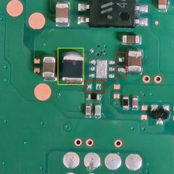
Agitated, I tried to blow hot air while ironing, then boom, hot air blew some small components(red outline) away. I was able to get larger component back in place, but I'm not sure about the direction of it(yellow outline).
So...
-TL;DR : My 2500 slim has dead 'Wi-Fi step-down converter'. I'm pretty confident about it. But in my failed repair attempt I lost some components around it, and now I need to find replacement for them, too.
So here I am. With lost components. Could someone tell me what those black and gray(?) components are? I'll try again with leaded solder(advertised as 183c melting point).
Yes, it cost me well over $50 already(especially in my labor), but for me the experience was worth it(playing techie was fun!). If it's not fixed even after second attempt, then there's repair shop as last resort.
*I'm in korea, so I probably can't follow some of your advices, such as recommendation of specific shops.
Link:
"Playstation 3 WiFi/Bluetooth repair" Youtube Video
Image description:
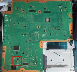
1. Overview of motherboard(JTP-001 variant), Area of interest is outlined as red square.
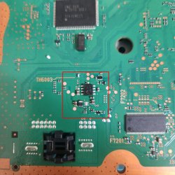
2. Closer view of step-down converter area.
3. Zoomed shot of converter area. Shot with digital zoom of my phone. Sorry for crappy quality.
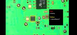
4. Screenshot of youtube tutorial video. Lost components are outlined.
* Long-winded "How I ended up here" ahead. Skip to TL;DR part if you're not interested. Sorry for bad english(and literature).
One day my friend brought me his 2500 slim, with wireless(Wi-Fi/BT) function lost. I didn't know what the problem was, and tried reinstalling firmware to 'fix' it. Got 8002F1F9, googled frantically and finally learned the cause : dead wireless module(in my case).
I tried several '8002F1F9 fix'(including hdd pull trick and putting in another hdd trick), and I was able to get back to recovery mode and install NOBT firmware. So it boots normally again. But, I wanted OC firmware and that had no NOBT variant, and maybe he would need bluetooth function. I contacted professional repair service first, but the price was over $50,
So I decided to go cheap and googled for wifi fix, and mainly got "You have to replace whole module"(and wireless module for 2500 is hard to find, let alone how difficult the replacing work is), but there was a video that suggests a step-down converter around the module could be the culprit. I tested voltage around as the video says, and confirmed 5 volts input, but 0.x volt output - Luckily, maybe I could get away with just replacing the converter!
With help of plenty flux and hot air, removing the chip was easy enough(used cheapo aliexpress 8898 solder station). But when I tried to wick old solder away and add new solder(unleaded, my mistake) with my iron, the solder just solidified and won't stick on the pads(even with over 400c setting).
Agitated, I tried to blow hot air while ironing, then boom, hot air blew some small components(red outline) away. I was able to get larger component back in place, but I'm not sure about the direction of it(yellow outline).
So...
-TL;DR : My 2500 slim has dead 'Wi-Fi step-down converter'. I'm pretty confident about it. But in my failed repair attempt I lost some components around it, and now I need to find replacement for them, too.
So here I am. With lost components. Could someone tell me what those black and gray(?) components are? I'll try again with leaded solder(advertised as 183c melting point).
Yes, it cost me well over $50 already(especially in my labor), but for me the experience was worth it(playing techie was fun!). If it's not fixed even after second attempt, then there's repair shop as last resort.
*I'm in korea, so I probably can't follow some of your advices, such as recommendation of specific shops.
Link:
"Playstation 3 WiFi/Bluetooth repair" Youtube Video
Image description:
1. Overview of motherboard(JTP-001 variant), Area of interest is outlined as red square.
2. Closer view of step-down converter area.
3. Zoomed shot of converter area. Shot with digital zoom of my phone. Sorry for crappy quality.
4. Screenshot of youtube tutorial video. Lost components are outlined.