Doubts about the update loop

Paul7

Forum Noob
I recently managed to repair a PS3 Slim CECH-3001A that did not turn on and did not show the red led light, I found two shorts in the capacitors in the area marked in YELLOW, so I removed them both, thanks to this the console managed to turn on and accessed the menu XMB and even released a game that was inside the console.
My questions are, if I removed these capacitors, how will it affect the console in the future? At the time of updating the console, may it give me an error since it checks if there is any failure in the components that are in the MOBO?
Captura.PNG
 
it's leadfree solder to conform with green laws to protect the environment, so it wasn't exactly sony and microsoft's fault.

I just went through my backported games. some don't work, so I'm going to have to see if I can fix them. control is obviously a no go. I think trials rising might be as well, but I'm not sure. all I got was a black screen. sorry, off topic. :D

I recently managed to repair a PS3 Slim CECH-3001A that did not turn on and did not show the red led light, I found two shorts in the capacitors in the area marked in YELLOW, so I removed them both, thanks to this the console managed to turn on and accessed the menu XMB and even released a game that was inside the console.
My questions are, if I removed these capacitors, how will it affect the console in the future? At the time of updating the console, may it give me an error since it checks if there is any failure in the components that are in the MOBO?...
I started a thread but it seems to be in revision. I'm sorry to put it in this thread, but I wanted to know if you know anything about this?
 

Attachments

  • Captura.PNG
    Captura.PNG
    1.1 MB · Views: 29
Last edited:
First you need to see the pinout of that connector... and try to deduce which functions could stop working by the damage you have
This PSU's are the posible PSU models for your PS3 model CECH-30xx.. the pinout is the same in both anyway
https://www.psdevwiki.com/ps3/APS-306
https://www.psdevwiki.com/ps3/EADP-185AB

And take a look at this schematic too, is from a CECH-25xx but i bet in CECH-30xx is pretty much the same, in it you can see where are connected that pins of the white PSU connector
https://www.psdevwiki.com/ps3/File:SYSCON_SWx_JTP-001_JSD-001_HSW-001_CN101.jpg

Hello Sandungas, I hope you are well, thanks for the information you provided me, I was reviewing and comparing it and indeed the PSU of this PS3 is the APS-306 with the serial on a pink sticker. I also took the time to review the schematic you provided but it seems that the two micro-capacitors I removed are not represented in it, but I am not 100% sure. I attach the images that I took where I hope you can appreciate the space where I removed the micro-capacitors. I will also highlight it so that it can be seen more easily.
As you can see the arrangement of the pins (marked in blue) is in good condition, I was very careful when removing the micro-capacitors taking into account that I removed them with a soldering iron, since I do not have a heating station.I also attach a video (Gif) where you can see that the console turns on, but I have not used it for long periods of time since I have no idea if the micro-capacitors were very important or if using the console without them would be counterproductive.
 

Attachments

  • Inked20200813_113006_LI.jpg
    Inked20200813_113006_LI.jpg
    1.4 MB · Views: 33
  • Inked20200813_113028_LI.jpg
    Inked20200813_113028_LI.jpg
    1.5 MB · Views: 34
  • 20200811_125327GIF.gif
    20200811_125327GIF.gif
    4.9 MB · Views: 268
I dont know the circuit from memory good eought to figure what are those components removed
But i guess one of them was a capacitor for the +5VSB (5 volts standby always enabled). This is the voltage that feeds the syscon chip

Without it the syscon could become inestable... the syscon is like a processor, eventually it could get stucked internally (like a freeze/crash inside syscon)... when that happens the console becomes irresponsive to the ON/OFF button pressess. So eventually the console could refuse to boot or things like that
Is easy to "wakeup" syscon by unpluging (and pugin again) the main power cord... when you remove electricity from the motherboard the syscon "resets" and returns to normal behaviour
Ok I understand, then the most advisable thing would be to solder new capacitors in the place where the previous ones were, to update the console in this case and to avoid those possible Crashes or freezes? Thank you very much for taking the time to answer my questions btw.
 
I have a JSD-001 motherboard (from a PS3 model CECH-25xx) in front of me... and using your photos as reference...

The pin located most at south in the white connector is 5VSB
The next pin is GND
The capacitors are soldered in paralell (this means they works as a single capacitor), and are connected in between 5VSB and GND
And my tester indicates a total capacitance* of 25.48uF

The total capacitance indicates the sum of the capacitances of the 2 capacitor you removed + another 2 tiny capacitors next to them + the capacitance of the circuit + other posible components i could be missing

The correct way to meassure them accuratelly would be to desolder them to meassure them "offboard" (not connected to anything, this way we isolate them individually)... but im not going to desolder them, sorry

Okay thank you very much Sandungas, there is no need to apologize, I just wanted to know in essence what could happen when leaving the console without the capacitors, however with the information you provided I can find a way to replace them later, in the same way I`ll not use the console until they are replaced. Again, thank you very much for all the information and for taking the time to try to solve my doubts.
 
Okay thank you very much Sandungas, there is no need to apologize, I just wanted to know in essence what could happen when leaving the console without the capacitors, however with the information you provided I can find a way to replace them later, in the same way I`ll not use the console until they are replaced. Again, thank you very much for all the information and for taking the time to try to solve my doubts.
I guess are something around 10uF each (so 2 of them are 20uF or so) and the other 5.48uF up to the 25.48uF displayed by my tester is caused by the "surrounding" components

So i guess it can be fixed if you solder a single capacitor of 20uF in between 5VSB and GND... or wait for someone to reply to this post with the correct value (there is people in this forum that does PS3 repairs and have tons of junk PS3 motherboards, and they could desolder them to meassure them)
Incase you have a tester to meassure capacitance try to recycle it from some junk device/toy you could have at home

Incase you decide to dont fix it... keep an eye at the posible weird things that could do the PS3 when you either turn it ON or OFF
The purpose of them is to stabilize the power input of syscon chip, so if you notice something weird related with syscon... yeah is better to fix it
 
...if you notice something weird related with syscon... yeah is better to fix it
Im going to explain this a bit better because is interesting and is going to help you identify the posible problems you could have in the future, my guess is you could have 3 different types of problems

Problems when syscon changes his "power states"
I dont know for sure, but most probably syscon have at least 2 power states, one of them is the normal operation mode (when most subcircuits inside syscon chip are enabled), and the other is the "low power" mode when the PS3 is in standby (fan stopped, and RED led)
The syscon changes his power state at the same time you turn ON/FF the PS3... at that point syscon is going to change his voltage requirements

Problems when syscon does some special procedures
Probably there are some operations where all/most of the circuits inside syscon are active... right now i dont know much about this

Problems when your PSU gets old
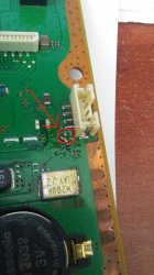
PSU---> capacitors---syscon
Glacier ---> lake ---> your house

The lake stabilizes the amount of water that goes to your home
Incase the glacier works "fine" (generating always the same amount of water) then you could remove the lake
But if the glacier have periods where it doesnt generates any water... and you remove the lake... then you are not going to have water at home in that periods

So... by removing the capacitors you are making the syscon more sensible to the variations of voltage generated by the PSU
Now it works fine because your PSU seems to be in good state... but eventually when your PSU gets older you could have problems in syscon, and at that point you will have to:
-Add the capacitors (and squeeze a bit more of the PSU lifetime)
-Replace the PSU
 
Last edited:
Back
Top