PS3 Fault finding YLOD with the SYSCON - First steps and Error reporting

What do you compare or think to enable any extra info on a pci ? it will even be possible ?ive been looking to compare pins as well.
Im brainstorming about this because yesterday i was updating some pages in wiki related with this and i realized there are some problems in wiki

First thing that called my attention was the "service connector" pinout that can be seen at bottom of this page https://www.psdevwiki.com/ps3/Service_Connectors#CN.3F.3F.3F.3F_v1
Is the same connector that can be seen at left in one of your photos
0ez5bPe.jpg

PS3_Service_Connector_VER-001-small.jpg

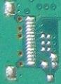
In theory (as explained in wiki), that connector have pins for the syscon UART... but thats not true for motherboard JTP-001/JSD-001 (i dont know if it was true for previous motherboard models)
Pins 10,11,12,13 of this "service connector" are not really connected to syscon

And right now im wondering if pins 4,5,6 (for southbridge UART) are wrong too... because as we was discussing the southbridge UART is accessed by sony with the "80 pins PCI connector"

-----------
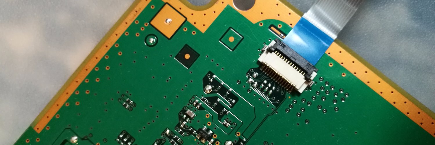
The second wiki problem is the PCI pinout that can be seen in this page https://www.psdevwiki.com/ps3/PCI
As you can see it doesnt matches with the photo i uploaded in my previous post
 
Last edited:
i will do some data research with time.
Dont worry, i just realized about something that was confusing me, check this link again, i just updated the page, and click in the links at the right cells of the pinout table that says "lines xxx disconneced"
https://www.psdevwiki.com/ps3/Service_Connectors#CN.3F.3F.3F.3F

Yesterday i realized that there are 3 missing components in the JTAG lines (pins 7,8,9) because his solder pads are located very close to the service connector
But i didnt realized there are another 4 missing SMD components at the other side of the motherboard for the UART lines (pins 10,11,12,13)

So... the pinout in wiki for that "3rd gen service connector" is right, we could make the UART connections in it, is just the solder pads are smaller than the others

Btw, that pads are intended to solder a connector of this type, i dont know the name of it, but if some of you find it and you are skilled enought to solder it i think it could be a nice geek upgrade :D
Service_connector_3rd_gen_VERTIGO.jpg


----------
Edit:
I also made this image for completionism, i think the names "tx" and "rx" are assigned correctly
25uYKR8.jpg[img]
 
Last edited:
Ffc or fpc connector , if I order from China those types I look for type with moving clamp or if cable goes inside and clamp is pushing inside over cable. First off need to know what pitch and number of pins.
EDIT
I have assumed those pins for SB are right .
@CodeKiller are they right?
I will also reserch over pdf datasheet in renesas can't remember model ; zecoxao give me 4 months ago references.I remember also factory have disabled development for entire rom at one specific address of this type of renensas .
 
Last edited:
Hello and good day to the people of this thread (and the psx-place as a whole).
I am watching this thread for some time and first I want to say that the things you people are doing here are amazing (especially with all this recent "right to repair" push) – really huge job was done by the community members and you just keep going on without a rest! Much respect.

I tried my best to caught up to date on this thread, however there are too many messages, so, I have a small silly question:
Okay, basically, is this the old and beaten up question about the right USB to TTL serial converter cable for the job (since it was written multiple times that you can kill your SYSCON chip with improper voltage).

I just want to check with you on this:
From these messages I can assume that I am all good and this is the right cable for the job:
Question: is my USB to TTL serial converter (and its voltages) will do the job fine (and will not fry the SYSCON chip in the process)?
Thank you for your time,
 
Btw, that pads are intended to solder a connector of this type, i dont know the name of it, but if some of you find it and you are skilled enought to solder it i think it could be a nice geek upgrade :D
Service_connector_3rd_gen_VERTIGO.jpg

These are useful I you want to do some debugging on syscon:
Dl8e9c7XsAAhLQk
 
Hello and good day to the people of this thread (and the psx-place as a whole).
I am watching this thread for some time and first I want to say that the things you people are doing here are amazing (especially with all this recent "right to repair" push) – really huge job was done by the community members and you just keep going on without a rest! Much respect.

I tried my best to caught up to date on this thread, however there are too many messages, so, I have a small silly question:
Okay, basically, is this the old and beaten up question about the right USB to TTL serial converter cable for the job (since it was written multiple times that you can kill your SYSCON chip with improper voltage).

I just want to check with you on this:
From these messages I can assume that I am all good and this is the right cable for the job:
Question: is my USB to TTL serial converter (and its voltages) will do the job fine (and will not fry the SYSCON chip in the process)?
Thank you for your time,

Yes this will work fine, discard the 5v red wire, you dont need it. just TXD,RXD and GND. GND can be connected to any part of the metal chassis or pin on the mother board.

I recommend AWG 30 cable when connecting these wires to the motherboad to usb ttl lead.
 
@db260179 How do i get inside SB uart on phat/slim boards ? It should work while system is running ? I'm asking as I haven't tested any until now. Later I will come over here with some errors of ps4 board on media com and i will seek some suport.
 
@db260179 How do i get inside SB uart on phat/slim boards ? It should work while system is running ? I'm asking as I haven't tested any until now. Later I will come over here with some errors of ps4 board on media com and i will seek some suport.

You have to connect on the SB uart pins first, then enable debug mode on 0x7202 0x02 = w 7202 02 (for FAT models)

This redirects logging to the SB uart - its a read only view when using serial from the SB uart.

More details on https://www.psdevwiki.com/ps3/SC_EEPROM - search for 0x48C0, in section:
Dumpable SC EEPROM Offset - Block ID and Block Offset Mapping Table (NVS Service)
 
How do i get inside SB uart on phat/slim boards ? It should work while system is running ? I'm asking as I haven't tested any until now. Later I will come over here with some errors of ps4 board on media com and i will seek some suport.

You have to connect on the SB uart pins first, then enable debug mode on 0x7202 0x02 = w 7202 02 (for FAT models)

Mullion 201GB, 202GB: 0x7202
Mullion 203GB + later : 0x4202
Sherwood : 0x1202

This redirects logging to the SB uart - its a read only view when using serial from the SB uart.
It's used for writing stuff but only on specific firmwares.

You can also activate some lv1 debug messages (level 0x00 to 0x03) to get more information by changing the 0x48CF0 to 0x48CFF NVS offsets.
 
is that for all SC versions? or does that not matter here?

It only depends on the main firmware version, as long as you run anything higher than 0.90 it'll work.
0x00/0xFF means off; 0x01, 0x02, 0x03 are different levels (warning, info, debug). I typically set the first one to 0x03 and then the ones I'm interested in also to 0x03.
This will produce a lot of messages and is only really useful if you're doing research on special (late) error cases.
I used it e.g. to get an idea why prototype syscons can't be remarried or how the VSH Target works.
It'll allow you to get messages from the PME secure services, not from the main Hypervisor code (which does things like RSX init etc.), this would require CFW.
 
So I was finally able to pull codes from my b01 console!

The codes are A0801001,1004,and 1704.

Would that be indicative of a failing power supply?
85254cb1347b8fffc3ce04a337de4c5c.jpg


Sent from my SM-G965U using Tapatalk
 
As a quick update to my question above I tried switching power supplies and it will still only stay powered on for about 50 seconds (stop watch) it then makes a very small clicking noise like a tiny relay is clicking open and it goes back to the solid red standby light.

Sent from my SM-G965U using Tapatalk
I'd start by checking your fuses... The cecha01 service manual should be close enough to assist in locating those.
 
I'd start by checking your fuses... The cecha01 service manual should be close enough to assist in locating those.
Luckily I downloaded those a long time ago lol

But would a bad fuse allow the system to remain on for almost a minute? When its on I get an occasional hdd activity light (especially right before shutting down), the usb ports are active (controller lights flash when plugged in), and it gets hot just like a stock a or b model ps3 would.

Sent from my SM-G965U using Tapatalk

interesting! yeah, you did mention that it would run for 50 seconds... that, and the 80 state in the error code indicates a full power up. I should have payed more attention before I replied :)

If you boot into maintenance mode, does it stay running for longer than 50 seconds?
 
Luckily I downloaded those a long time ago lol

But would a bad fuse allow the system to remain on for almost a minute? When its on I get an occasional hdd activity light (especially right before shutting down), the usb ports are active (controller lights flash when plugged in), and it gets hot just like a stock a or b model ps3 would.

Sent from my SM-G965U using Tapatalk

Using the service manual for this board - COK-001, you will need to check the fuses around the CELL area, top and bottom.
Then check the voltage lines - 12v,5v and 3.3v.

Trace the 12v first on the top of the board, check each cap that links to the 12v line, any showing a short will indicate an issue.
Most of the power controller is on the top of the board - focus around the CELL as this is indicating an issue.

Couple extra things to check, do a resistance check on the 12v and GND pins (unplugged), it should do a creeping resistance from 4.3k, swap the leads on the multimeter, should start from 0 then climb. If it reads or stays at a resistance then there is a short on the board.

Again check the CELL area, I suspect there is a dodgy cap thats shorted.

Worse case scenario, the CELL is gone bad or the PCB inner layer has shorted, which is known for the first revision boards.
 
Can this be confirmed SB pinout for rxtx cok002?
I may be wrong but is only point where 3v3 it goes on board and fuse or that resistance is uninstalled from factory.
259154012dd66136363f80ecb7f13fd5.jpg
 
interesting! yeah, you did mention that it would run for 50 seconds... that, and the 80 state in the error code indicates a full power up. I should have payed more attention before I replied :)

If you boot into maintenance mode, does it stay running for longer than 50 seconds?
Well here's my problem with this console, it was on ofw 2.35 and I went to update it to 4.86 when all this happened. So since it was pre 3.55 there is no safe mode sadly. It just sits there and warms up like they do and then clicks back to the red standby light at about 50 to 52 seconds

Sent from my SM-G965U using Tapatalk
 

Similar threads

Back
Top