Hi there
I've got another untouched fat (which seems to work fine for now), installed CFW and pulled the syscon error log.
Quite weird errors, all dated Jan.30. 2006 and all are somehow (RSX, CELL and Southbridge) thermal related...
Error Log
01: A0802131 Mon Jan 30 21:44:30 2006
02: A0802031 Mon Jan 30 21:44:17 2006
03: A0802130 Mon Jan 30 21:41:58 2006
04: A0802130 Mon Jan 30 21:41:57 2006
05: A0802030 Mon Jan 30 21:41:52 2006
06: A0802030 Mon Jan 30 21:41:43 2006
07: A0802131 Mon Jan 30 21:41:38 2006
08: A0802031 Mon Jan 30 21:41:27 2006
09: A0802131 Mon Jan 30 21:41:13 2006
10: A0802031 Mon Jan 30 21:41:09 2006
11: A0802030 Mon Jan 30 21:41:07 2006
12: A0802131 Mon Jan 30 21:40:49 2006
13: A0802130 Mon Jan 30 21:40:36 2006
14: A0802131 Mon Jan 30 21:40:30 2006
15: A0802131 Mon Jan 30 21:40:24 2006
16: A0802130 Mon Jan 30 21:40:13 2006
17: A0802030 Mon Jan 30 21:40:09 2006
18: A0802131 Mon Jan 30 21:40:06 2006
19: A0802031 Mon Jan 30 21:40:04 2006
20: A0802030 Mon Jan 30 21:39:59 2006
21: A0802131 Mon Jan 30 21:39:55 2006
22: A0802031 Mon Jan 30 21:39:46 2006
23: A0802031 Mon Jan 30 21:39:37 2006
24: A0802131 Mon Jan 30 21:39:35 2006
25: A0802130 Mon Jan 30 21:39:34 2006
26: A0802030 Mon Jan 30 21:39:29 2006
27: A0802130 Mon Jan 30 21:39:23 2006
28: A0802131 Mon Jan 30 21:39:05 2006
29: A0802130 Mon Jan 30 21:38:40 2006
30: A0802030 Mon Jan 30 21:38:37 2006
31: A0802131 Mon Jan 30 21:38:36 2006
32: FFFFFFFF Fri Dec 31 23:59:59 1999
I wonder if someone else have seen this kind of errors... @Pacorretaco maybe?
Did they run or test the boards without heatsink/fan at the factory?
Or is the date/time stamp maybe CMOS battery related, i.e. does the PS3 reset to January 2006 if the battery is empty?
Best regards
I am not sure, but I wouldnt pay much attention to those errors.
When you have working machine that has no problems and you take a look at the log... Well, you get non-errors.
Better leave the log for when there are real problems. But even then, the errors that are "not" there may give more information than the random ones that "are" there.
Anyway, you tell us... Observe the machine and tell us if there is something weird going on that could explain those errors and make us understand them better.
Otherwise I'm not a big fan of chasing problems that aren't there haha, (Voodoo, etc) as you may already know.
That cummulation of garbage is the kind of thing that looks weird visually but could not be related with your problem at all
Is flux or varnish that becomes liquid when the board overheats, the console was placed horizontally and the board was a bit wrapped... so the liquid flows to the most lowest point of the board, and then "drops" like an stalactite
But it seems all that liquid comes from the border of the board
So... the location is completly random, it doesnt means the components in that area are overheating either
Actually, in your photo it can be seen the liquid comes from the border at top (where the HDMI, AV, LAN, and all the other back conectors)
Btw, at the botom-right of your photo is the RSX, and the 2 big data buses connected to it that goes up are for the HDMI and AV controller chips (this chips doesnt overheats as far i now)
Clean it with isopropil alchol and a toothbrush anyway, the flux is not electrical conductive but when it was liquid and it was sliding it could cummulate dust particles, crap, and even some shard of metal that could create interferences in the pins of the dirty components
Thank you very much for your advise sandungas. I've managed to get some isopropil alcohol and cleaned the board as best as I could. There was remaining flux around RSX and BE, which led me to think that in the past this board may have been reballed. Unfortunately, after all the cleaning, I'm still getting the same errors:
-A0233020
-A0203010
I don't know where to start looking at this point, as there are no other components that catch my eye. I hope someone can help me with this.
I guess you already was taking a look at the comments in the wiki page Syscon Error Codes
3010 and 3020 are together with some more errors that are simply labeled as "CELL" because thats the official description but we dont know what they means
Initially seems to be related with power lines, there is also a note under 20 3010 mentioning that the error can be triggered (for troubleshooting testing) sy sabotaging a "buck controller"
The 20 (or 23) located inmediatly after the A0 in your errors indicates that it happens at an early step of the boot process (i guess while the console is running some checks to the power lines)
All and all... im not sure which components could be involved with this problem, but the diagnostic should be positive, probably is going to be easy to repair
You know... it seems to be a general problem, we dont know if your PS3 is going to trigger more errors codes at a later point of the boot sequence (that coud require a rebaling of CELL or RSX) because the boot sequence is stopping soon, but probably CELL and RSX are fine because the probabilityes for several components of the motherboard to start failing at the same time are small
Thank you very much for your quick response sandungas, I will keep looking for the source of the problem in case it can expand the general knowledge about this error. At the moment, I'm following some of the videos from the YouTube channel that pacorretaco shared in recent posts. I'm taking measurements of the resistors and voltages following the videos. If I come across anything interesting I'll let everyone know!
Here is the problem, I had to start with it first I unsoldered it and started without a sensor - a new error A0A02033 came out, the old A0001214 was gone. I replaced it with the thermal sensor from the working motherboard and cheers the console started. But not for long .. it shuts off after 10-20 seconds - new error A0801002. I soldered 3 cables to the Cell, RSX NEC capacitors and ground and hooked up to 3000uF. This time the console starts for longer. About a minute. And again off - new errors A0801103 and A0A02031, Temperatures - tmp 0 and tmp 1.
The fan was spinning at very low speeds. I don't know for what reason, but I connected +12 to the PWM of the fan and it worked at maximum. I already had the opportunity to install a HHD and firmware.
EDIT: I installed custom firmware and set the fans to 30%, 40%, 50% .., but again it turns off from overheating, but not from the processor or GPU.
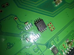
After taking some voltage and resistance measurements according to some videos, there is a resistor in particular that makes me doubt about its condition. In particular, it is the one that I highlight in the following image:
When I measured it yesterday, it was giving me 0 Ω. That was when I started suspecting. Today, I measured it again once I got home, and it was giving around 4 Ω (pretty low in my opinion). Did some voltage measurements while turning on and off the console, measured once again and 0 Ω. The resistor seems to be part of a low pass RC filter (maybe not, I don't remember very much from my electronic lectures). Maybe I should try replacing it, but I don't know its value, as there is nothing written on top of it.
By doing some research on the service manual of the COK-001 board, I found a similar low pass RC filter near the CPU that I indicate in the following image. In this case, resistor is in one side of the board while capacitors are on the other side.
Unfortunately, the resistor appears in the circuit diagram marked with "xx". Is it because it is a 0 Ω resistor? or maybe I'm misunderstanding something?
If by any means anyone knows if this could be the source of my error messages, or maybe someone with a KTE-001 could measure that resistor for me, I would be profoundly thankful.
I got a yellow light CECHA01 off craigslist and I pulled A0213013 and A0801001. I checked F6302 and it's good, but F6301 is blown. My C4004 also appears to be shorted. Do these have any correlation to either code? What else should I check? Thank you so much in advance!
Hello,
Motherboard DIA-002. Instant YLOD. Errors 1002 and 3003.
After a short warm-up with a hair dryer on the back of the RSX chip, the console starts in 10 seconds with error 2120. On a new start - either starts in 2-5 seconds or YLOD.
Then YLOD again until I warm up with the hair dryer and start again for a few seconds.
I think the problem is BGA defect, but I wanted to ask anyway.
Quick preface... Having come back around to the scene here after many years, just wanted to extend a congrats to everyone who has pushed forward the collective ability to diagnose and repair these consoles to an extent orders of magnitude beyond the previous level. Amazing work. Looking forward to the replacement top element for by BGA station to arrive and get to work on getting the 65 and 40nm donor boards here to work.
OK, so I have a CECHE01 in front of me. Purchased with an intact warranty seal. Boots up, no YLoD... and that's it. No video (HDMI, Component, composite), no BT, nothing. I haven't really had a GLoD appear to be so alive, yet so dead simultaneously. Sysconned into internal mode, and the below results were quite unhelpful.
Further investigation reveals all 8 tokins are 2.7 or 2.8ohms... and some death valley level thermal compound.
Oddly enough, the fan (15 blade) and PSU (ZSS) were both the bottom of the barrel, so I'm assuming this is an earlier E model. I haven't (in bygone years) seen this combo in an E very often... but that's certainly not saying much after being away from these consoles for so long.
This time I got another cok-002 mobo for equivalent of ~2 beers, only downside is that backside looks like it was sitting in a barn for 10 years and I'm not sure what it needs to be working again.
It has only 425 hours on it, but almost 1500 power on cycles and spits out thermal errors. I haven't tested it with any daughter boards, only with PSU, mobo cleaned with IPA. Still looks bad, but nothing is missing etc, but I think there was some corrosion under the SYSCON chip, right next to battery connector, so most likely reflow (or reball if I find a stencil for this package) incoming.
Error log:
Looking at psdevwiki I found: "Speculation: 2030-33 errors reported in case of dodgy PWR/EJT daughter board.", I never even had this board connected to it. There is a lot of grime around that area, but it doesn't really come off with IPA - I mean it looks better, but far from what I would say good.
EDIT: I forgot to mention, BE heats up normally, SYSCON corrosion was at more or less R4037 level, maybe a bit shifted to C4057, reflowed R4031 and R4030 and probably 83/84 also, voltage on R4031 rises to 3.3V (dead syscon?), on R4030 0.45V, after idling one minute:
949 days, but yet the error log is barren. I can't wrap my head around how the power delivery topology still gives the appearance of being in good condition. If this would be a time for a tokin failure mode, or at least laughable resistances, I'd have assumed such a state. I haven't yet moved into the SB uart direction, but given the lack of information I currently have, I see no other alternative from which I can derive any useful diagnostic data.
A couple other points of interest:
+ No BT controller sync
+ I can hear and see with duty get 0 the fan changing speeds in relation to temp fluctuations
+ Tried multiple HDDs, the HDD activity LED does blink a few times upon boot
+ Recovery Mode/Video out reset appears to function normally sans any video output (beep patterns, etc.)
+ VRM Thermal Pads are toast, SB+PS2 pads are fine
22,778 hours of runtime with an intact warranty seal. What an odd thing, this board. None of the normal GLoD ailments but with all the symptoms.
.....
In the same shipment I received the antithesis console which was hung up on just a bad HDD and was on fw 3.61:
Code:
> becount
becount
Bringup : 199 times
Shutdown: 103 times
Power-on: 17day 18hour 05min 26sec
[mullion]$
Well, my results have shown so far that the YLOD due to tokins is throwing an 80 1002. It had the bad waveform on RSX side and a slightly bad waveform on the CPU side. It once threw a 1001 and a 1004 has occurred a couple of times in testing various combinations of removing/replacing tokins/other caps.
So maybe it means you have bad CPU tokins like we were originally thinking, but I'm not so sure with my latest round of tests. I replaced every tokin on the RSX side and reduced the bad waveform to one I would consider good, but it still threw 1002's. Now I'm removing CPU tokins and replacing with TaaPol arrays and it's getting better (RSX noise is actually lowering, the CPU bad waveform is gone), but it's still throwing 1002 errors at varying lengths of time in game play (random YLOD under normal stress).
I still have 1 CPU tokin to remove and 2 TaPol arrays to install before I know more, but so far I'm beginning to suspect that the CPU and RSX tokins/noise are more related than previously thought. You can't just replace one tokin on one side based on an error code, like 1001 means replace the CPU tokins, or 1002 means replace the RSX trokins. More like if you have a 1001 or 1002 and 1004's mixed in with those two, replace all the tokins. It's an all or nothing kind of deal. Don't mix and match! I've noticed that the filter really hates mixing different capacitors. Keep them all the same.
Did you solve this? I have a SEm-001 that had 1002 so I replaced the NEC's on the RSX rail and it still throws a 1002! It is the first time I have encountered it
Did you solve this? I have a SEm-001 that had 1002 so I replaced the NEC's on the RSX rail and it still throws a 1002! It is the first time I have encountered it
If I remember correctly that was PS3 #7. @squeept traded me that board, which had genuine tokin fault after he reballed the RSX. I performed a bunch of characterization of the tokin noise using that console before the reball failed.
Basically the Cell noise can leak through to the RSX side and amplify it. Alternatively the VRM can be going bad. Also there is a 1st stage RC filter that amplifies the effect of the 2nd stage LRC filter the tokins are a part of. So those need to be good.
Power Control Topology - Part 3
(SYSCON Switches and Power On Sequencing)
Introduction:
You may have heard of the term booting a computer. But what actually is taking place is more complex thatn you may realize. The term "BOOT" actually refers to a "bootloader" program that loads the operating system (OS). But before the Bootloader can start, the console must first be able to enter standby. Then it needs to clear Power On Sequence Testing (POST).
When you plug in your PS3, or flip power rocker at the back, the Power Supply Unit delivers power to System Control (SYSCON) and a crystal for it's clock. There are also some thermal monitors and analog voltage regulators needed for the most basic standby functions. What's happening is the SYSCON is powered and waiting. The LED goes solid red. The Bluetooth subsystem is powered so that you can start the console with your controller. The PS3 is just waiting for you to press the power button. If your PSU is dead or the fuses to those Analog Voltage regulators are blown, then you wont even get into Standby!
When you turn the console on it goes through a process called Power On Sequence Testing (POST), which includes 2 processes.
Power On Sequencing (POS): The SYSCON "switches" on voltages to the console subsystems one at a time. They need to be powered on in a certain order, and configured properly before the next system can be powered and configured. In this way the console's bringup is coordinated.
Power On Reset (POR): A series of signals and configuration data that synchronize the chipset. For example, the CPU/GPU/SB are held in reset until the clocks and power supplies have been "switched" on (enabled) by SYSCON and their output has stabilized (Power Good). Then reset is released and the chipset will startup synchronized. Then they will be ready for initialization and configuring.
Once the console has cleared POST the bootloader can begin loading the operating system.
Of course that's the simplified explanation! It doesn't do us much good when you are having an issue and need to track down the culprit. Thanks to theSYSCON errorlogs, we now have error codes that give us information about the problem. More specifically, there is a 4-digit code that points to a particular area. We have already discussed that in great detail.
I recently collated 250+ consoles worth of data and presented an analysis. What I learned is that many of the 4-digit codes overlap. They don't always tell you what you want to hear - That your NEC/TOKINs are bad, or there is specific fuse that needs replaced. Instead it narrows down the list to a number of possabilities. You still need to troubleshoot the board (continuity, resistance, ESR of electrolytic caps, voltages, etc). And you need to observe the console history. Has it been opened? What work has been done? What are past errors in the errorlog telling you? This context leads us to a better diagnosis.
What's less understood and probably more useful in the 2-digit Step Number just before the 4-digit error. For example 20 2120. All the 2120 tells us is that the error is related to the HDMI transmitter. So does that mean the HDMI chip is dead? Well, that depends on context. How does it look? Are there shorts, missing voltages, blown fuses, flux residues, what other errors are in the log? That can help rule out lots of potential issues.
Step# 20 tells us when error 2120 occurred! It tells us if the error occurred in Standby, POST, BOOT, System ON, or System Off states. It's the key to understanding the meaning of the 4-digit error code, because knowing what the console was doing when the error occurred provides vital context. If that step is when the SYSCON switches on a voltage regulator, then it could be a fuse that blew.
And that's exactly what has been reported to happen with errors 202120 /213013. At Step# 20 SYSCON switches on IC6301, which powers up DC/DC converters for the AV Backend. This I/O subsystem is known to cause 2120 errors, but the Step# tells us where to look first. Since it occurred when the SYSCON first enables those voltages, we should really suspect the fuses and voltage regulators. So focus your attention on probing that area. Sure enough, users have reported this error combination can be caused by blown F6302, short C6320, etc. That theose voltages were not present when they attempted to power the console on.
On the other hand, If the same error occurs at a different Step#, it can mean something completely different. For example, @db260179 reported a 00 2120. 2120 is the same 4-digit HDMI error, but the Step# 00 refers to standby. For context, he got the error as soon as he plugged in the console, not when turning it on. He repaired by replacing TH2501, which protects +5V_ANA voltage for the HDMI port. He noted with it blown, IC2501 regulator on pin 6 (HDMI Initialize) is not getting anything. I don't believe he ever mentioned if the replacing the fuse fixed that console or not. It's possible that a bad HDMI cable, or it got knocked, cause a short blowing that fuse. There could have been more damage. The point is, this was the same 2120 error with a completely different issue. The Step# was the only thing that might have clued us in. That is if we weren't preoccupied looking at the HDMI chip and RSX power (tokin or BGA). We were too focused on guessing that we missed a simple fuse. This emphasizes the need to troubleshoot the board THOROUGHLY! Check fuses!!!
"Get on with it!"
So now we know the Step# is important, we just need to know what each Step Number means. What is the console doing?
We have been having this discussion for awhile now...
He's referring to this IBM Hardware Installation Guide for the 65nm CELL CPU. I read it pretty thoroughly and inferred the general "cytology" from their "example." It seems like it needs to follow most of that general order. It is highly technical an took several days to even begin to wrap my head around it, but very helpful to understand the Attention, Hard reset, Machine Checkstops, and Livelock signals.
While SONY may not have stuck to the HIG, there is a great deal on information in there about the required sequencing. Anyway, between the HIG and the SYSCON codes I put together the following. Like yours, it' definitely not 100% accurate or anything. Just me attempting to organize the step numbers in context of SYSCON switches and what the console is doing.
I understand if that's TMI! It's a complicated process. And that was just IBM's example. As @M4j0r pointed out, SONY deviates from it. That only complicates matters for us. If this interests you at all, I did make an effort to translate the above information in terms of the PS3. To follow is the rotten fruit I yielded...
Initialization Sequence – AKA Power On Sequence Testing (POST).
It may be easier to visualize this using the following voltage flowchart. I have been updating it as I learn more about the console. @sandungas, you were asking about this in another thread, so here you go. View attachment 35986
SYSCON drives POWER_GOOD and HARD_RESET signals to 'low'.
Power supplies and reference clocks are activated sequentially. SYSCON Switches...
SW_0 = +5V, +3.3V, & +1.7V MISC
SW_1_A = +3.3V_MK_VDD for Clock Synthesizer
SW_1_B = +2.5V_LREG_XCG_500_MEM
Analog Voltage for the core PLL of IC5004, Clock Generator used to support the Rambus XDR memory subsystem and Redwood logic interface.
The Cell BE power supplies must be turned on in the following order:
SW_6 = +1.2V_YC_RC_VDDIO (I/O voltage supplies, VDD_IO)
SW_7_A = +1.0V_BE_VDDC (Cell BE core voltage supply (VDD) then VCS (the core array voltage). Note, the VID values stored on the CELL itself are not available to be read yet. So the default VID of the VRM is used until then.
SW_8_A = +1.5V_YC_RC_VDDA (Analog voltage supplies, VDD_A)
The RSX power supplies must be turned on in the following order:
SW_8_B = +1.5V VDDIO for both AVCG & RSX Analog IO
SW_8_C = +1.8V_RSX_PLL_VDD
Initialize the Cell BE core logic
Reset the internal state
Set up the core phase-locked loop (PLL)
Adjust the VRM voltage according to the voltage identifier (VID) information stored in the Cell BE processor. The CPU is ready to set the VID dynamically now. From SW_7_A to this point takes about 130ms.
Load the configuration-ring data.
Calibrate the FlexIO interface (initialization, BitTraining, and byte calibration).
Initialize the I/O interface.
Execution of code on the PowerPC Processor Element (PPE).
Initialize the extreme data rate (XDR) I/O cell (XIO) memory interface
Initialize dynamic random access memory (DRAM)
Initialize PPE hardware-implementation dependent (HID) special-purpose registers (SPRs).
Load FW/OS
Done, System loads into XMB and the console is rockin.
I'm still trying to fugure how the step numbers fit in.
A more simplified overview:
When you use the bringup command in Mullion SYSCONs there are SSM states that seem to indicate when the SYSCON performs certain actions. I made a simplified overview using them...
000 -> 101
Power sequence setup called
12 steps (00 - 11 & 20).
101 -> 201
AV Backend Setup
201 -> 102
2 steps (21 & 22)
SW_8_B & SW_8_C enable AV Backend DC/DC convertes.
HDMI Transmitter initialization. Confirmed using HDMI VFB command in SYSCON.
+1.5V_RSX_VDDIO is POR for DVE
102 -> 202
Doesn't have any steps? I don't have an explanation for this.
202 -> 103
2 steps (23 & 30)
23 2102 = Fatal RSX Error (IC2001)
Must be some kind of RSX initilization/checks.
103 -> 203
CPU Livelock setup
203 -> 104
3 steps (31, 32, & 40)
load Configuration Ring Data.
31 3032 = BE Initialization error. Reported when a user knocked R5167 off. +1.2V_YC_RC_VDDIO reference voltage for the CPU's Redwood FlexIO Controller reference clock (BE_RC_REFCLK_P).
Calibrate the FlexIO
40 3034 = CPU/GPU (FlexIO) Power Failure (YC_RC_VDDIO) Usually caused by a BGA defect. These are the SPI voltage lines that connect the CPU/GPU.
40 4xxx = Data error (FlexIO). Usually caused by a BGA defect. These are the SPI DATA lines that connect the CPU/GPU.
Psbd_SbTransMode_Full:0x20e2
4 steps (50-52 & 60)
50 3035 = Occurred on a console exhibiting 3034/4002 then after a failed reflow attempt 232102. After a pressure test the console GLOD with the 503035. There is an 80 1002 in there too.
60 3040 = NAND/NOR Flash Memory, where the OS firmware is stored. The OS can't load if the chip containing it isn't powered. This would be one of the last checks before the power on state is reached, because a power failure here would prevent the boot loader from initializing.
104 -> 204
Doesn't have any steps? I don't have an explanation for this
204 -> 105
3 Steps (61, 62, & FF)
105 -> 400
Power On State
The console is powered on and ready to continue with the boot loader.
Digging in deeper:
And here I attempted to really dive into exactlt what's happening at each Step Number...
SYSCON Reset
A0 = 2030, 2031, 2033, 2124, 2131.
When the power Rocker is flipped on, IC6004 receive +5V_EVER directly from the PSU. It produces /SYSCON_RST automatically.
An error immediately after SYSCON reset probably indicates an issue with the following...
SYSCON Reset serves as enable for IC6009, which is forms +3.3V_THERMAL for RSX/CPU/SB Thermal Monitors.
IC6005/6 are also powered by +5V_EVER and produce +3.3V_EVER and 1.8V_EVER respectively.
SYSCON Switches on Clocks and Power Supplies (DC/DC converters)
SYSCON runs "Bringup", "OnStartingBePowOn()", and "PowerSeq_Setup" which enables clocks and DC/DC converters. SYSCON SW Lines control most of the DC/DC converters. SYSCON waits a certain period of time for the voltages to stabilize and Power Good. After that, SYSCON will error at any point if there is a power fail signal on any of the main voltages it's directly monitoring.
Errors can occur during successive step numbers if the new load and noise generated causes a previously good voltage to fall out of regulation (AC coupling, common mode noise, insufficient decoupling/bypassing, etc). So error codes may overlap with later step numbers.
Note: I don't know which step number corresponds to which Switch exactly, but that could be figured out by sabotaging each DC/DC converter to trigger an error. Here's what we know from reported SYSCON errors..
05 = SW_4 (Ethernet, USB, SB Peripherals, and SB PLL)
06 = SW_5 (Power RSX VRM, default VID)
07 = SW_6 (XIO/FlexIO Reference Voltage)
08 = SW_7 (Power CELL VRM, default VID)
09 = SW_8 (CPU/SB/RSX MIC/BEI Analog Voltages)
A = +1.6V_BE_VDDA & +1.5V_YC_RC_VDDA. MIC & IOIF Analog Voltages. These Controllers interface Analog signals with the digital Core over the FlexIO interface.
10 = PS2 Bridge Chip? (Switches its own subsystem)
11 = Maybe just finishing up initialization of the thermal monitors? IDK. One user had 2131 from a dead thermal monitor that gave an error with this step #. He replaced it to fix.
Initialize CPU/RSX Core and Adjust VRM to VID. AV Backend
Step# 20
SYSCON Initializes the RSX core, VRM adjust voltage acording to VID, and the AV backend initializes. If the RSX is dead or missing it returns 20 1802.
20 = SW_8 (RSX)
B = +1.5V_YC_RC_VDDIO, +9V_ANA, +5V_ANA, +3.3V_ANA & +1.8V_ANA. Analog Voltages for MultiAV Digital Video Encoder (IC2406), Audio DAC (IC2405), & HDMI Transcoder (IC2502).
+1.5V_RSX_VDDIO acts as Power On Reset for the DVE (MultiAV).
C = RSX PLL Voltage and thermal monitor initialization.
SYSCON enables and sets up the HDMI Transmitter. It communicates over I2C.
Step# 21
Errors reported with Step# 21 = 3010 & 3013 (CPU voltage related)
SYSCON enables the CPU's Core and VRM adjust voltage acording to VID.
SYSCON allows a timing delay after enabling IC6103, to account for Soft Start and PWRGD formation (for the voltage to stabilize). I'm not sure how long that procedure takes, but once PWRGD is formed the normal rise time adds about 10µs (RC time constant). 3010 appears to be the error when PWRGD is formed too quickly.
@DeadEnd got a 20 3010 injecting 3.3v on BE_POWGD. SYSCON didn't like that the timing delay was 0µs. It shouldn't have come back so quickly.
@Kleon1876 had a 21 3013 when he damaged a CPU trace while deliding. It caused a BE_SPI DI/DO ERROR - CELL not communicating to syscon via SPI. Many others have had 3013 errors associated with 20 2120. Usually associated with Reflows or Mods involving the CPU (eraser mod). Check MC2 VDDIO Bypassing (C1444-1453).
Differential Signal Power sequencing for BE_RC_REFCLK is needed for timing the FlexIO interface before proceeding to Bit Training. User @Bbowes had error 31 3031 on a console that shorted RSX:TX1 to ground. That shorted the entire FlexIO reference voltage (+1.2V_YC_RC_VDDIO), preventing checks at this step. He also had 31 3032 by accidentally knocking R5167 off, which disrupted the True side of Differential reference clock pair output (IC5004 Pin 24, BE_RC_REFCLK_P). I guess that the Complementary side of Differential reference clock pair output (IC5004 Pin 23, BE_RC_REFCLK_N), who's external resistor network can be disrupted by knocking off R5170, would generate error 31 3033. But that should be tested to confirm.
BitTraining Calibrates the FlexIO interface, which is how the SB/CPU/RSX communicate.
Initilize the IO Interface
Errors reported with Step# 50 - 52 = 3035
Errors reported with Step# 60 = 3040
CPU/SB/RSX to begin coordinating and initializing over the I/O interface.
Really not sure what's happening here. I guess the POR is checking to be sure it completed correctly and everything is setup.
End of POST.
Load Firmware and OS
Errors reported with Step# 61 = 1101 & 1802
Bootloader runs and Southbridge accesses the FW stored on NAND. Not sure how the rest of this goes. But if it all goes well the operating system loads.
Any power related issue that causes the voltage to fall out of regulation, such as excessive ripple/noise can trigger a YLOD.
Any unresolved CPU errors can cause BE Attention signal to go high. The SYSCON immediatly shuts off the console, then reads the SPI Status Register to determin the cause. Then it records the an error A0801701 in it's errorlog. Errors that can cause the Attention include...
Unresolved Checkstop errors (14FF)
Livelock Detection (1601)
PLL Unlock Condition (1301)
BGA/Bump Defect that occurs while the Console was On (Step# 80). Subsequent attempts to power on the console would result in 3034/4xxx errors.
Hypothesis: System settings are saved, and the console powers down. If an error prevents the settings from being saved, the SYSCON will throw an error during this state. Often there are HDMI errors during this step. If BGA defects affect the VDDIO line between the RSX and HDMI Transmitter, it will not be able to save user selected video configuration to the EEPROM on the SYSCON. It stalls during the waiting operation beyond the expected delay, SYSCON assumes there's a problem and issues a 90 2120 error (for example). Upon next boot the video setting reverts to its previous state.
The following is just here because I don't have a great place to put them. But I still wanted to get it out there for completeness.
Clock Synthesizer (IC5001)
Powered by +3.3V_MK_VDD.
A 14.31818MHz input crystal (X5001) provides a reference clock from which 4 PLLs generate System clocks.
MK_USB_CLK = USB Clock
SB_SYSCLK = South Bridge System Clock
SB_PCI_CLK = South Bridge PCI Clock
SB_PCI0_CLK = South Bridge PCI0 Clock
SB_SS2_CLK = South Bridge / Starship2 Clock
BC_PCI_CLK = PS2 Bridge Chip PCI Clock
RSX_PLL_REFCLK = Processor Clock
YRCG0 = Yellowstone / Redwood Clock Generator 0
MK_XCG0 = XDR Clock Generator 0
<-- BE_PLL_VDDA
--> BE_PLL_REFCLK (IC5003)
MK_XCG2 = XDR Clock Generator 2
<-- +1.2V_YC_RC_VDDIO
--> SB_RC_REFCLK (IC5004)
--> RSX_RC_REFCLK (IC5004)
--> BE_RC_REFCLK (IC5004)
YRCG1 = Yellowstone / Redwood Clock Generator 1
MK_XCG3= XDR Clock Generator 3
--> BE_Y0_RQ (IC5002)
--> BE_Y1_RQ (IC5002)
XDR 2-Differential Pair Clock Generator (IC5002)
Powered by +2.5V_LREG_XCG_500_MEM.
XCG_EN à EN Pin 11. Where is this sent from?
SMBus Address bit 0 (ID0 Pin 12) is tied High & SMBus Address bit 1 (ID0 Pin 13) is tied High. This sets the output control register bits to enable clock output on differential pairs 1 and 2 (BE_Y0_RQ and BE_Y1_RQ) and read from device 0. Question: What does this accomplish?
/BYPASS Pin 14 is tied High for PLL Mode
XDR 2-Differential Pair Clock Generator (IC5003)
Powered by +2.5V_LREG_XCG_500_MEM.
XCG_EN à EN Pin 11. Pulled High by R5048 when +2.5V_LREG_XCG_500_MEM is present.
Default SMBus Address select 1 (ID0 Pin 12) is tied low & Address select 2 (ID0 Pin 13) is tied Low. This designates a read operation on device 0 (BE_PLL_VDDA). It also sets the operating mode to Hi-Z, disabling the output.
/BYPASS Pin 14 is tied High for PLL Mode
XDR 4-Differential Pair Clock Generator (IC5004)
Powered by +2.5V_LREG_XCG_500_MEM.
XCG_EN à EN Pin 11. Where is this sent from?
SMBus Address bit 0 (ID0 Pin 12) is tied low & SMBus Address bit 1 (ID0 Pin 13) is tied High. This forms the device ID and designated operation. In this case a read operation on device 3 (RSX_RC_REFCLK and YC_RC_VDDIO). Question: What does this accomplish?
Hello Gents,
I have a CECHC onto which I soldered a 40nm RSX (without IHS, the one with "RSX" engraved on it).
Steps related to SMD resistors and vreg are done.
(not sure about 47k resistor though, needed or not?).
I enabled the syscon internal mode and modified values for RSX 40nm (without IHS).
And... -> RSX bittraining error occurred.
Then I tried values for RSX 40nm (with IHS)
And... no bittraining errors. POS completes, but no video output and console shuts down after 1min WITHOUT any errors in the errlog.
Anyway, the console does not give any video output.
Literally... it gets stuck after POS -> BootLoader between SSM 400 -> 500.
MultiAV and HDMI sil were replaced as well.
CELL/BE tokins replaced with tantals.
Would you happen to be so kind and look at the syscon log in the spoiler below?
What happens between SSM 400 and 500?
The post quoted above states "calibrating I/O", and I see that hdmi is "waiting for resolution".
We're out of ideas here.
This time I got another cok-002 mobo for equivalent of ~2 beers, only downside is that backside looks like it was sitting in a barn for 10 years and I'm not sure what it needs to be working again.
It has only 425 hours on it, but almost 1500 power on cycles and spits out thermal errors. I haven't tested it with any daughter boards, only with PSU, mobo cleaned with IPA. Still looks bad, but nothing is missing etc, but I think there was some corrosion under the SYSCON chip, right next to battery connector, so most likely reflow (or reball if I find a stencil for this package) incoming.
Error log:
Looking at psdevwiki I found: "Speculation: 2030-33 errors reported in case of dodgy PWR/EJT daughter board.", I never even had this board connected to it. There is a lot of grime around that area, but it doesn't really come off with IPA - I mean it looks better, but far from what I would say good.
EDIT: I forgot to mention, BE heats up normally, SYSCON corrosion was at more or less R4037 level, maybe a bit shifted to C4057, reflowed R4031 and R4030 and probably 83/84 also, voltage on R4031 rises to 3.3V (dead syscon?), on R4030 0.45V, after idling one minute:
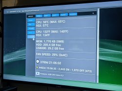
I did some tests on that motherboard, washed it a couple of times and even got somewhere. This board is still very fussy, but at this point I sometimes have sync signal on HDMI and 14FF error on syscon (earlier 3010). I also noticed that the RSX/CELL temps are 0x0110 and 0x002c respecively, I once run it without heatinks for a while, but I don't think long enough to damage CELL.
")