Like I said in my post I did hundreds of times that dose not make a difference and they are makeing a good connection because I checked with a multi meter my issue is not that I can't with it's that I can't even see the com when I connect the ps3 but when I disconnect it I can see it it just dosent workSometimes you need to swap Rx and Tx
You are using an out of date browser. It may not display this or other websites correctly.
You should upgrade or use an alternative browser.
You should upgrade or use an alternative browser.
PS3 Fault finding YLOD with the SYSCON - First steps and Error reporting
i dont know if it would help but i could try and do a video or discord call and show you if you are willing because i cant really use my work bench till i figure this out so i can do it wheneverConnect GND from PS3's outter copper parimiter to the Uart GND. This way both PC and PS3 share the same ground refrence.
sorry i keep posting over and over like a crazy ex but i did everything again but for a diffret ps3 i did it on a launch modle modle cechbo1 i think and everything worked like a charm but then i hook up the ps3 slim 21xx-40xx and suddenly my pc says usb detection error any time the ground is connected to the ps3 very off issueConnect GND from PS3's outter copper parimiter to the Uart GND. This way both PC and PS3 share the same ground refrence.
i have a ps3 slim with a glod. everything looks like its working correctly except video out. i get a searching for signal with the hdmi when powered up but no signal shortly after, and a black screen with the av.
>$ AUTH
Auth successful
Press Ctrl+C to exit
>$ errlog
00000000
# CODE CLOCK
# A0902024 0B49D849
# A0802124 0B49D849
# A0802024 0B49D800
# A0802024 FFFFFFFF
# A0802124 FFFFFFFF
# A0802024 FFFFFFFF
# A0402024 FFFFFFFF
# A0002024 FFFFFFFF
# A0A02024 FFFFFFFF
# A0A02124 FFFFFFFF
# A0A02024 FFFFFFFF
# A0A02124 FFFFFFFF
# A0A02024 FFFFFFFF
# A0A02024 FFFFFFFF
# A0A02024 FFFFFFFF
# A0A02024 FFFFFFFF
# A0A02024 FFFFFFFF
# A0A02024 FFFFFFFF
# A0A02024 FFFFFFFF
# A0A02024 FFFFFFFF
# A0A02024 FFFFFFFF
# A0A02024 FFFFFFFF
# A0A02024 FFFFFFFF
# A0A02124 FFFFFFFF
# A0A02124 FFFFFFFF
# A0A02124 FFFFFFFF
# A0A02124 FFFFFFFF
# A0A02124 FFFFFFFF
# A0A02124 FFFFFFFF
# A0A02124 FFFFFFFF
# A0A02124 FFFFFFFF
>$ bringup
00000000
# [SSM] Bringup Start.
Press Ctrl+C to exit
>$ bringuplog
F0000003
# [SSM] PS0 ok.
# [SSM] PS1 ok.
# [SSM] PS2 ok.
# [SSM] PS3 ok.
# [SSM] PS4 ok.
# (PowerOn State)
OK 00000000
#!
#!Boot Loader SE Version 3.0.0
#!(Build ID: 3684,41778,
#!Build Date: 2009-08-28_22:53:58)
#!
#!Copyright(C) 2009 Sony Computer Entertainment Inc.All Rights Reserved.
#!
#![INFO]: Connecting to Debug Device (SB UART)
# [UCMD] Unknown command.
Press Ctrl+C to exit
>$ bringup log
FFFFA605
Press Ctrl+C to exit
>$ bringuplog
F0000003
# [UCMD] Unknown command.
Press Ctrl+C to exit
>$ powerstate
00000000
# ATA :ON
# PCI :OFF
# PCIex:OFF
# RSX :ON
# GDDR :ON
# XDR :ON
# EURUS:ON
# SB :ON
# LAN :ON
# WLAN :ON
Press Ctrl+C to exit
>$ tmp get 0
00000006
Press Ctrl+C to exit
>$ tmp get 1
00000006
>$ hdmi chstat 0
00000000
# ----------------------------
# -- HDMI Channel 00 Context --
# ------------------------------------------------------------------------------------
# +-[System Management]
# - SSM Task ID : 000C
# * Task Status : WAITING
# * Wait Cause : EVENT FLAG
# - SSM State : UnPlg
# - SSM Semapho Information : ID[0021] WaitTID[0000] semcnt[0001]
# - SSM Event Flag Info : ID[0016] WaitTID[000C] FlagPattern[4000]
# - SSM Mode : Unknown
# ------------------------------------------------------------------------------------
# - Authentication Status : NotStart
# - Repeater : Sink
# - KSVs : 0000
# ------------------------------------------------------------------------------------
# +-[Interrupt]
# - Interrupt Mask Pattern in MN864709 : 8
# 00 00 00 00 00 00 00 00
# - Interrupt Register Size : 08
# - Interrupt Task ID : 0002
# * Task Status : WAITING
# * Wait Cause : EVENT FLAG
# - Semapho Information : ID[001E] WaitingTID[0000] Count[0001]
# - Plug Status : UnPlug
# ------------------------------------------------------------------------------------
# +-[MNType]
# - Chip Type : Unknown
# ------------------------------------------------------------------------------------
# +-[EDID]
# - EDID Sema ID : 20
# - Semapho Information : ID[0020] WaitingTID[0000] Count[0001]
# - EDID Block Size : 0000
# ------------------------------------------------------------------------------------
# +-[I2C Bus]
# - Device Address 5
# 70 72 7A 7C 7E
# - Semapho Information : ID[001F] WaitingTID[0000] Count[0001]
# ------------------------------------------------------------------------------------
# +-[AV Setting]
# - Audio Setting State : Unset
# Mute ; Mute
# - Video Setting State : Unset
# Mute ; Mute
# Setting : 12
# 00 00 00 00 00 00 00 00 00 00 00 00
# : 00 00 00 00 00 00 00 00 00 00 00 00 00 00 00 00 00
#
#
are both the encoders dead?
disk drive is unplugged btw. not sure if thats why the pci and pciex are off or not.
Andrydon95
Forum Noob
Hi, I have a ps3 FAT 80 GB DIA 002 with immediate YLOD, I have already replaced all the NEC Tokin with 4 470 tantalum for each NEC. I had Syscon errors 3001 and 3003 but after jumper with tantalum I only have error 3003, what should I do?
boa tarde,
Tenho um PS3 cecha com erros 1004/3004, todas as voltagens da placa estão ok, exceto a voltagem rsx 1.2v nos nectokins. Verifiquei a página 25 do manual, todos os componentes estão ok, o ic6201 é responsável por liberar os pwms para o ic6202 e ic6203, ele não está liberando, tenho voltagem 12v no pino 22, e voltagem enable no pino 29.
O ic6204 é responsável por ativar o ic6202 e ic6203 também funciona bem, depende do pino 8 e pino 29.
Portanto, não tenho tensão nos pinos gate para pwm do ic6202/ic6203.
A questão é: o ic6201 pode ser uma maçã podre?
porque pelo que vi esse CI, os pinos 1,2,3,30,31,32 em uma certa sequência formam um código que indica qual tensão deve ser comparada, mas não sei se essa tensão define se o pwm seria liberado ou não.
good afternoon,
I have a PS3 cecha with errors 1004/3004, all the voltages on the board are ok, except the rsx 1.2v voltage on the nectokins. I checked page 25 of the manual, all components are ok, ic6201 is responsible for releasing the pwms for ic6202 and ic6203, it is not releasing, I have 12v voltage on pin 22, and enable voltage on pin 29.
The ic6204 is responsible for activating the ic6202 and ic6203 also works well, it depends on pin 8 and pin 29.
So I have no voltage on the gate to pwm pins of the ic6202/ic6203.
The question is: could the ic6201 be a bad apple?
because from what I saw of this IC, pins 1,2,3,30,31,32 in a certain sequence form a code that indicates which voltage should be compared, but I don't know if this voltage defines whether the pwm would be released or not.
Mod edit: Provide an English translation with your post.
Uau!, ainda é YLoDing, mas foi um pouco mais longe:
[CÓDIGO]>$ lasterrlog
[SSM] estado: 0000 -> 0101
Modo Bringup #0 (0xFF)
[SSM] chamada ssmCb_OnStartingBePowOn().
[SSM] Primeira inicialização.
[SSM] Modo de inicialização: syspm_stat=00000000/00000000
[POWSEQ] Chamada PowerSeq_Setup.
[SSM] estado: 0101 -> 0201
[POWSEQ] Configuração de backend AV
[SSM] estado: 0201 -> 0102
[SSM] estado: 0102 -> 0202
[SSM] estado: 0202 -> 0103
[SSM] estado: 0103 -> 0203
[SSM] ssmCb_BeforeBeOn() chamado.
[SSM] estado: 0203 -> 0104
Psbd_SbTransMode_Meio:0x21e2
[POWERSEQ] Erro: BitTraining BE:RRAC:RX2:GLOBAL1:RX_STATUS
[SSM] estado: 0104 -> 0304
[SSM] ssmCb_AfterBeOn2() chamado.
[SSM] Falha PowSeq: Detectada!
[SSM] estado: 0304 -> 0700
[POWSEQ] AV Backend Acalmado
[SSM] Modo de desligamento: syspm_stat=00000000/00000000
[ERRO]: 0xa0404421
[ERRO]: 0xa0403034
[POWSEQ] PowerSeq_Letup chamado.
[SSM] estado: 0700 -> 0600
(Estado desligado) (Fatal)
último registro
Último código de erro: 0xa0403034, hora: 0xffffffff[/CODE]
Adivinhe, parece que o IC6202 talvez não esteja quebrado, afinal. O C6225 estava em curto (acho que bati nele enquanto removia os Tokins, não tomei cuidado) e, como consequência, o R6240 também foi danificado (ele tem 2,2 Ohm, mas li mais de 1 KOhm). Substituí o C6225 por um equivalente, e o R6240 por um de 3 Ohm (eu não tinha resistores de 2,2 Ohm).
Então, alguma dica sobre os erros 0xa0404421 e 0xa0403034? Eles estão na categoria "erro de dados", então será que eu tenho que montar a coisa?
EDIT: Hum, não vi exatamente o mesmo código de erro (404421), mas parece que preciso de uma nova versão... mais notícias.
Last edited by a moderator:
i have a ps3 slim with a glod. everything looks like its working correctly except video out. i get a searching for signal with the hdmi when powered up but no signal shortly after, and a black screen with the av.
>$ AUTH
Auth successful
Press Ctrl+C to exit
>$ errlog
00000000
# CODE CLOCK
# A0902024 0B49D849
# A0802124 0B49D849
# A0802024 0B49D800
# A0802024 FFFFFFFF
# A0802124 FFFFFFFF
# A0802024 FFFFFFFF
# A0402024 FFFFFFFF
# A0002024 FFFFFFFF
# A0A02024 FFFFFFFF
# A0A02124 FFFFFFFF
# A0A02024 FFFFFFFF
# A0A02124 FFFFFFFF
# A0A02024 FFFFFFFF
# A0A02024 FFFFFFFF
# A0A02024 FFFFFFFF
# A0A02024 FFFFFFFF
# A0A02024 FFFFFFFF
# A0A02024 FFFFFFFF
# A0A02024 FFFFFFFF
# A0A02024 FFFFFFFF
# A0A02024 FFFFFFFF
# A0A02024 FFFFFFFF
# A0A02024 FFFFFFFF
# A0A02124 FFFFFFFF
# A0A02124 FFFFFFFF
# A0A02124 FFFFFFFF
# A0A02124 FFFFFFFF
# A0A02124 FFFFFFFF
# A0A02124 FFFFFFFF
# A0A02124 FFFFFFFF
# A0A02124 FFFFFFFF
>$ bringup
00000000
# [SSM] Bringup Start.
Press Ctrl+C to exit
>$ bringuplog
F0000003
# [SSM] PS0 ok.
# [SSM] PS1 ok.
# [SSM] PS2 ok.
# [SSM] PS3 ok.
# [SSM] PS4 ok.
# (PowerOn State)
OK 00000000
#!
#!Boot Loader SE Version 3.0.0
#!(Build ID: 3684,41778,
#!Build Date: 2009-08-28_22:53:58)
#!
#!Copyright(C) 2009 Sony Computer Entertainment Inc.All Rights Reserved.
#!
#![INFO]: Connecting to Debug Device (SB UART)
# [UCMD] Unknown command.
Press Ctrl+C to exit
>$ bringup log
FFFFA605
Press Ctrl+C to exit
>$ bringuplog
F0000003
# [UCMD] Unknown command.
Press Ctrl+C to exit
>$ powerstate
00000000
# ATA :ON
# PCI :OFF
# PCIex:OFF
# RSX :ON
# GDDR :ON
# XDR :ON
# EURUS:ON
# SB :ON
# LAN :ON
# WLAN :ON
Press Ctrl+C to exit
>$ tmp get 0
00000006
Press Ctrl+C to exit
>$ tmp get 1
00000006
>$ hdmi chstat 0
00000000
# ----------------------------
# -- HDMI Channel 00 Context --
# ------------------------------------------------------------------------------------
# +-[System Management]
# - SSM Task ID : 000C
# * Task Status : WAITING
# * Wait Cause : EVENT FLAG
# - SSM State : UnPlg
# - SSM Semapho Information : ID[0021] WaitTID[0000] semcnt[0001]
# - SSM Event Flag Info : ID[0016] WaitTID[000C] FlagPattern[4000]
# - SSM Mode : Unknown
# ------------------------------------------------------------------------------------
# - Authentication Status : NotStart
# - Repeater : Sink
# - KSVs : 0000
# ------------------------------------------------------------------------------------
# +-[Interrupt]
# - Interrupt Mask Pattern in MN864709 : 8
# 00 00 00 00 00 00 00 00
# - Interrupt Register Size : 08
# - Interrupt Task ID : 0002
# * Task Status : WAITING
# * Wait Cause : EVENT FLAG
# - Semapho Information : ID[001E] WaitingTID[0000] Count[0001]
# - Plug Status : UnPlug
# ------------------------------------------------------------------------------------
# +-[MNType]
# - Chip Type : Unknown
# ------------------------------------------------------------------------------------
# +-[EDID]
# - EDID Sema ID : 20
# - Semapho Information : ID[0020] WaitingTID[0000] Count[0001]
# - EDID Block Size : 0000
# ------------------------------------------------------------------------------------
# +-[I2C Bus]
# - Device Address 5
# 70 72 7A 7C 7E
# - Semapho Information : ID[001F] WaitingTID[0000] Count[0001]
# ------------------------------------------------------------------------------------
# +-[AV Setting]
# - Audio Setting State : Unset
# Mute ; Mute
# - Video Setting State : Unset
# Mute ; Mute
# Setting : 12
# 00 00 00 00 00 00 00 00 00 00 00 00
# : 00 00 00 00 00 00 00 00 00 00 00 00 00 00 00 00 00
#
#
are both the encoders dead?
disk drive is unplugged btw. not sure if thats why the pci and pciex are off or not.
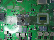
I have a CECH2002A with the same symptoms (powers on fine, responds normally to discs etc. but no video/audio over hdmi or the multi av out) and same error codes.
I compared the board to another I have and the hdmi encoder is shorted to ground on a bunch of the pins when compared to another YLOD unit. I have not tried to swap the encoder from the other board onto this one.
Did you make any progress with yours?
Code:
>$ errlog
00000000
# CODE     CLOCK
# A0802024 FFFFFFFF
# A0802024 FFFFFFFF
# A0802124 FFFFFFFF
# A0802024 FFFFFFFF
# A0A02124 FFFFFFFF
# A0A02024 FFFFFFFF
# A0A02024 FFFFFFFF
# A0A02024 FFFFFFFF
# A0802024 FFFFFFFF
# A0802024 FFFFFFFF
# A0802124 FFFFFFFF
# A0802024 FFFFFFFF
# A0902124 FFFFFFFF
# A0902024 FFFFFFFF
# A0902024 FFFFFFFF
# A0902024 FFFFFFFF
# A0802024 FFFFFFFF
# A0802124 FFFFFFFF
# A0802024 FFFFFFFF
# A0802024 FFFFFFFF
# A0802124 FFFFFFFF
# A0802024 FFFFFFFF
# A0A02124 FFFFFFFF
# A0A02024 FFFFFFFF
# A0A02024 FFFFFFFF
# A0A02024 FFFFFFFF
# A0802024 FFFFFFFF
# A0802024 FFFFFFFF
# A0802124 FFFFFFFF
# A0802024 FFFFFFFF
# A0A02124 FFFFFFFFI have a CECH2002A with the same symptoms (powers on fine, responds normally to discs etc. but no video/audio over hdmi or the multi av out) and same error codes.
I compared the board to another I have and the hdmi encoder is shorted to ground on a bunch of the pins when compared to another YLOD unit. I have not tried to swap the encoder from the other board onto this one.
Did you make any progress with yours?
Code:>$ errlog 00000000 # CODE CLOCK # A0802024 FFFFFFFF # A0802024 FFFFFFFF # A0802124 FFFFFFFF # A0802024 FFFFFFFF # A0A02124 FFFFFFFF # A0A02024 FFFFFFFF # A0A02024 FFFFFFFF # A0A02024 FFFFFFFF # A0802024 FFFFFFFF # A0802024 FFFFFFFF # A0802124 FFFFFFFF # A0802024 FFFFFFFF # A0902124 FFFFFFFF # A0902024 FFFFFFFF # A0902024 FFFFFFFF # A0902024 FFFFFFFF # A0802024 FFFFFFFF # A0802124 FFFFFFFF # A0802024 FFFFFFFF # A0802024 FFFFFFFF # A0802124 FFFFFFFF # A0802024 FFFFFFFF # A0A02124 FFFFFFFF # A0A02024 FFFFFFFF # A0A02024 FFFFFFFF # A0A02024 FFFFFFFF # A0802024 FFFFFFFF # A0802024 FFFFFFFF # A0802124 FFFFFFFF # A0802024 FFFFFFFF # A0A02124 FFFFFFFF
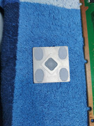
im still waiting on the encoder to come. i pulled the hdmi encoder and i get a screen that looks like https://images.app.goo.gl/fHEPBEiRuSJe8Wn16 except all white and black coming out of the av. i tried to link a picture but no dice on that. hopefully the chip will be here this week but maybe not.
NextJack0325
Member
RSX VDDC likeYoutube has a million basic multimeter tutorials to familiarize you with that part. So I'll let you figure that out.
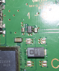
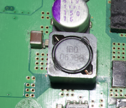
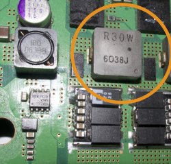
1002 implicates the RSX_VDDC, which is the core voltage for the GPU. Set your multimeter to resistance, continuity or diode mode and read the resistance across the +/GND rail on the NEC/TOKINs. If it reads the same resistance as when the probes are touching each other, then you have a short. But you would have a 3001 if that were the case, so you don't have a short. Normal resistance there should be 2- 3 Ohms or so. If it's less than 1, that's bad. It can indicate worn, oxidized or deformed solder joints that are nearing a fault (like a BGA/Bump defect), or it can indicate damage to the die circuitry from elcetromigration.
Here are some nominal resistance measurements from important voltage lines to the RSX. This and more can be found on Victor's private file pile.
View attachment 35320
If any of these are significantly different (say off by 10%) then there could be an issue with that voltage line. Check the scematics (also in Victor's treasure hoard) and track down the source of that voltage line and measure each resistor, capacitor and SMD for shorts. If they seem normal, it's probably an issue on/under the RSX itself. After removal the RSX can be "ohm tested" (each voltage drectly) to measure nominal resistance and verify it's okay before attempting to reball. That method is not !00% however, we'de really need a chip tester with pogo pins to measure every pad to know for sure. But this method is pretty good. But if you are going to that length, you may as well replace with a NOS 40nm RSX and mod chip.
EDIT: And here are the main RSX voltages and test points.

Now, most of that is a waste of your time. I'm pretty sure with those errors you need to replace the tokins. Start with one CPU and RSX tokin each. Remove them (carefully) and replace with 3 of these for each tokin replaced (24 per console if replacing all 8. Plan to do that anyway). Clean the Flux off thoroughly and then measure resistance again. If there is a short, you need to fix it before testing. That's basically all the multimeter is good for here - verifying you installed the TaPol caps correctly. Test the console after replacing one tokin on each side and see if your errors change. If not, replace one more tokin each. I'm betting the 3003/3004 disappears and you'll be left with a 1002.
If after the first or second tokin the errors change, the you know you're on the right track. Replace all of them and don't forget the bridge wires. Before, the tokins were acting as the bridge. If you don't provide a bridge wire after replacing all the tokins, the tantalum will explode (not kidding)! You don't have to worry about bridge wires if using my Tantalizer PCB, that's the main point. If you don't want to use it, I recommend a palisades arrangement like this...View attachment 35321
...but using the larger caps I linked before. It might be harder to fit them on, but you can make it work easy enough.
Lastly, the + rail's need a bridge wire. In the pic above I added a fairly large gauge (I forget now). But they will see a large current across them. They will burn out if not large enough. I used resistor legs to join the caps in the picture above, but I'd recommend at least a 16AWG solid core. A 65W RSX can generate 55 Amps. That's why it has 2 phase power. Each IOR power block can deliver a maximum of 40A. So it takes 2 of them to diliver the required power. The CELL CPU has 3 phases. I'm not sure how many watts it pulls, but guess around 100 Amps. That needs to be cunducted across the + rails, which will burn right through thin gauge wires. I looked it up, you would need 4x 8 gauge AWG wires to meet the 24A they could see at peak load. 8 guage is super thick. It's probably fine to go smaller, but I would just stick to my board for convenience. I made the + rail as wide as possable and the 0.8mm double thick copper is more than enought to handle any current demad the PS3 could need.
Hi/hello,
I have bought CECHC03 with YOLD.
When opened was very dirty, I have cleaned and made DELID and here surprise when take away IHS from RSX I saw 40nm chip.
When first time read errors I had 3001 and 1001
I have replaced PSU and NecTockin replace with a tantalum capacitors.
I have read syscon once more and got following errors
===================================
ERR 00: 00000000 A0403034 FFFFFFFF
ERR 01: 00000000 A0404421 FFFFFFFF
ERR 02: 00000000 A0403034 FFFFFFFF
ERR 03: 00000000 A0404421 FFFFFFFF
ERR 04: 00000000 A0403034 FFFFFFFF
ERR 05: 00000000 A0404421 FFFFFFFF
ERR 06: 00000000 A0403034 FFFFFFFF
ERR 07: 00000000 A0404401 FFFFFFFF
ERR 08: 00000000 A0403034 FFFFFFFF
ERR 09: 00000000 A0404421 FFFFFFFF
ERR 10: 00000000 A0403034 FFFFFFFF
ERR 11: 00000000 A0404401 FFFFFFFF
ERR 12: 00000000 A0003001 FFFFFFFF
ERR 13: 00000000 A0003001 FFFFFFFF
ERR 14: 00000000 A0003001 FFFFFFFF
ERR 15: 00000000 A0003001 FFFFFFFF
ERR 16: 00000000 A0003001 FFFFFFFF
ERR 17: 00000000 A0003001 FFFFFFFF
ERR 18: 00000000 A0003001 FFFFFFFF
ERR 19: 00000000 A0003001 FFFFFFFF
===================================
Any idea? Could happened something with RSX during DELID?
InHarmsWay
Forum Noob
Hey everyone, I have 2 ps3's (a01 & e01) that I delidded and replaced the tokins on. I delidded them first and tested for boot up and they were good. I replaced the tokins and now it's throwing a 2110 error. One had the f6001 fuse blow so I replaced it and c6019 & 6020. Nothing. I'm obviously doing something to cause it when I'm replacing the caps. Has anyone found how to fix 2110? I'm j-std certified so replacing anything isn't an issue but I have limited experience with tracking down shorts. Any help would be greatly appreciated!
Inextesia
Forum Noob
RSX side tokins. 118 days is too young tho! Thing must have been asphyxiated by dust...or a sauna PS3!
Thanks! And yes, it's really young because I didn't have games until I jailbreak it... Would I have a big issue if I continue to play without replacing tokens?
fmcampbell
Forum Noob
I own a CECHJ02 FAT PS3, which I've had for quite some time. About a year ago, after not using it for a while, I decided to set it up again. Unfortunately, I encountered the Yellow Light of Death (YLOD). Occasionally, the console does manage to boot; for instance, today, I powered it on to investigate the issue further. On the first attempt, I got the YLOD, but on the second attempt, it turned on successfully.
To troubleshoot, I used the PS3 Toolset to retrieve the error logs and compiled a numbered list of the errors, including how many times each occurred. I did my best to match the error codes to information I found on a wiki, but I'm not entirely sure if I labeled them correctly.
Now that I have this information, I need assistance in identifying the root cause of the issue and the steps I should take to resolve it. If more details are required, please let me know, and I'll do my best to provide them.
Code:
Error 3003 (CELL Core Power Failure) x13
Error 1001 (Power CELL) x17
Error 2014 (Unknown) x1

Error 0: 0xA0093003 Time: Tue, 26 Nov 2024 12:32:39 GMT
Error 1: 0xA0081001 Time: Tue, 26 Nov 2024 12:32:39 GMT
Error 2: 0xA0901001 Time: Mon, 15 Apr 2024 09:02:54 GMT
Error 3: 0xA0801001 Time: Sat, 13 Apr 2024 23:52:00 GMT
Error 4: 0xA0901001 Time: Sat, 13 Apr 2024 23:17:46 GMT
Error 5: 0xA0901001 Time: Sat, 13 Apr 2024 23:03:31 GMT
Error 6: 0xA0093003 Time: Sat, 13 Apr 2024 19:00:46 GMT
Error 7: 0xA0081001 Time: Sat, 13 Apr 2024 19:00:46 GMT
Error 8: 0xA0093003 Time: Sat, 13 Apr 2024 18:55:53 GMT
Error 9: 0xA0081001 Time: Sat, 13 Apr 2024 18:55:53 GMT
Error 10: 0xA0093003 Time: Sat, 13 Apr 2024 18:52:50 GMT
Error 11: 0xA0081001 Time: Sat, 13 Apr 2024 18:52:50 GMT
Error 12: 0xA0093003 Time: Sat, 13 Apr 2024 18:52:46 GMT
Error 13: 0xA0081001 Time: Sat, 13 Apr 2024 18:52:45 GMT
Error 14: 0xA0093003 Time: Sat, 13 Apr 2024 18:50:33 GMT
Error 15: 0xA0081001 Time: Sat, 13 Apr 2024 18:50:33 GMT
Error 16: 0xA0093003 Time: Sat, 13 Apr 2024 18:47:18 GMT
Error 17: 0xA0081001 Time: Sat, 13 Apr 2024 18:47:18 GMT
Error 18: 0xA0092014 Time: Sat, 13 Apr 2024 18:44:08 GMT
Error 19: 0xA0091001 Time: Sat, 13 Apr 2024 18:44:08 GMT
Error 20: 0xA0093003 Time: Sat, 13 Apr 2024 18:41:41 GMT
Error 21: 0xA0081001 Time: Sat, 13 Apr 2024 18:41:40 GMT
Error 22: 0xA0093003 Time: Sat, 13 Apr 2024 18:41:26 GMT
Error 23: 0xA0081001 Time: Sat, 13 Apr 2024 18:41:26 GMT
Error 24: 0xA0093003 Time: Sat, 13 Apr 2024 18:35:03 GMT
Error 25: 0xA0091001 Time: Sat, 13 Apr 2024 18:35:03 GMT
Error 26: 0xA0093003 Time: Sat, 13 Apr 2024 18:34:49 GMT
Error 27: 0xA0081001 Time: Sat, 13 Apr 2024 18:34:49 GMT
Error 28: 0xA0093003 Time: Sat, 13 Apr 2024 18:34:46 GMT
Error 29: 0xA0081001 Time: Sat, 13 Apr 2024 18:34:46 GMT
Error 30: 0xA0093003 Time: Sat, 13 Apr 2024 18:34:41 GMT
Error 31: 0xFFFFFFFF Time: Thu, 01 Jan 1970 00:00:00 GMTI have a CECH2002A with the same symptoms (powers on fine, responds normally to discs etc. but no video/audio over hdmi or the multi av out) and same error codes.
I compared the board to another I have and the hdmi encoder is shorted to ground on a bunch of the pins when compared to another YLOD unit. I have not tried to swap the encoder from the other board onto this one.
Did you make any progress with yours?
Code:>$ errlog 00000000 # CODE CLOCK # A0802024 FFFFFFFF # A0802024 FFFFFFFF # A0802124 FFFFFFFF # A0802024 FFFFFFFF # A0A02124 FFFFFFFF # A0A02024 FFFFFFFF # A0A02024 FFFFFFFF # A0A02024 FFFFFFFF # A0802024 FFFFFFFF # A0802024 FFFFFFFF # A0802124 FFFFFFFF # A0802024 FFFFFFFF # A0902124 FFFFFFFF # A0902024 FFFFFFFF # A0902024 FFFFFFFF # A0902024 FFFFFFFF # A0802024 FFFFFFFF # A0802124 FFFFFFFF # A0802024 FFFFFFFF # A0802024 FFFFFFFF # A0802124 FFFFFFFF # A0802024 FFFFFFFF # A0A02124 FFFFFFFF # A0A02024 FFFFFFFF # A0A02024 FFFFFFFF # A0A02024 FFFFFFFF # A0802024 FFFFFFFF # A0802024 FFFFFFFF # A0802124 FFFFFFFF # A0802024 FFFFFFFF # A0A02124 FFFFFFFF
alright got the new chip in and all the signals are showing good. havent gotten the hdmi to work yet but now i can get into recovery. no im getting stopped trying to reinstall the firmware. its asking for firmware 4.25 or newer, i throw 4.25 on the flashdrive (tried multiple). its set mbr/fat32, active. file is at PS3>UPDATE>PS3UPDAT.PUP. tried setting the allocation to16kb, default, and 4092. still get stuck with checking please wait until it says it cant find the file. tried a new hdd fresh out of the box too. tried the unplug the controller thing as well. im currently running through cex, dex, and ofw just because i have no way of telling whats on the thing. anyone have anything for my new issue? the old hdd let me rebuild the database but after or on normal boot it still only black screens. no new errors have been recorded either. they still all have the same 2024/2124 listed but thats probably from before.
updated: 11-30-2024
welp reflowed the rsx and got hdmi back. ran cex 4.25 and get error 8002f313.
Last edited:
Similar threads
-
 PS3 Kohada - A repair & tuning toolkit for the PS3 syscon
- Started by sagemono
- Replies: 2
-
 PS3 [Tutorial] How to use an ESP32 as a SYSCON UART Bridge
- Started by GrGeorge
- Replies: 0
-
-
