PS3 How to Enable Hidden Blue/Red Light in PS3 SLIM

Got mine done last night, big thanks to this thread i did not know about this mod. Looks awesome red and blue led :).

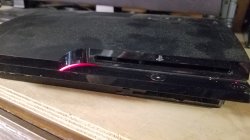
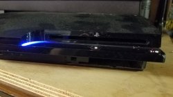
Hehe, nice, my CECH-25xx looks like that too, but without the red in standby, i considered the red could be a bit disturbing
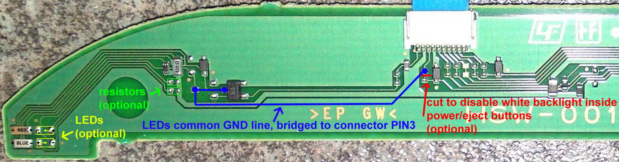
Btw, now that you have your hands in it, i suggest to use a big resistor for the red led to lower his intensity a bit and to make it less disturbing

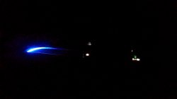
Is a shame the blue light doesnt spreads all along the line to the most right border of the console, i been wondering in doing this to try to achieve it:
-4x blue leds lighted together
-2x white + 2x blue lighter together

Not sure, maybe by doing this his intensity is going to be huge and thats not so good
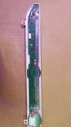
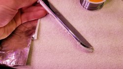
The alternative is to solder some wires in the led pads, and locate some of the leds all along the stripe (2 or 3), but maybe this is not going to look good enought either because there is going to be some points of the line where the leds are visibles :/
The goal would be to have a "difusse" light very well spreaded along the line... but to be honest im not sure how to do it, if someone have an idea please tell
 

Found out about this mod as well, and did it today out of curiosity.
However I did my own routing because I wanted red LED to glow when console is off, and blue LED when console is on.
Here is the routing I came up with:
unknown.png

https://imgur.com/a/w0W7s7X
Also, during the testing of various configurations, I somehow managed to screw up the eject button and now sometimes it completely goes wild. Did I screw up only the board or something else on mainboard? Going to purchase a replacement power board soon.
 
Last edited:
Just a couple of details...
The lenght of the wires can be shorted a lot if you solder next to the white plastic connector, keep in mind all the components of the circuit board have lines that goes into the white connector, so for most of them there are availables some "alternative" solder points next to the white connector

There are many different ways to do this mod, personally i wanted to have a blue light when the console is powered on but not a red light when is in standby. So instead of soldering into the green led i soldered in the line that drives the white leds

This is how i made it
Power_Eject_board_HSW-001_%28Enabling_contour_LEDs%2C_minimal_parts_version%29.jpg

-I didnt cutted the line marked in red
-I didnt added the missing resistors marked in green
-I didnt added the missing 2 leds marked in yellow
-I removed the red led (by destroying it with the solder iron)


So... i have a very short wire (the blue line)... i just have a blue led in that corner... and is turned on together with the white leds (only when the console is powered on)
 
Last edited:
I should also mention this since it's not very clear in the video, the Red standby LED that you can enable isn't nearly as bright as the Blue LED (personally I like this since it means it's not distracting in the dark when the PS3 is off).
 
In my HSW-001 the red led in the corner had lower intensity too, is because the value of the resistors
My plan was to replace the 2 resistors (and add 2 more) with something around 200ohm each, and replace the 2 leds (and add 2 more), all them in blue. This way the light in that corner should have the max intensity in a single color (to try to spread the light all along the horizontal line), i never did it though, and im not so sure if this would be enought to light all the horizontal line

This problem about the light not spreading smoothly all along the line doesnt seems to be the kind of problem that can be solved by bruteforce :D
 
Hi all!

I had to try this as I had some ideas. This is on a DSW-001 (CECH-2001A). Keep in mind this is on a scrap console, not the one that I play on. I figured if I were to let the smoke out, I'd rather have this one be the test subject. Basically it's a motherboard with a power supply inside the shell and that's it.
The sequence that I chose was to have both blue's come on with the White (Pwr & Eject) buttons and the red come on during standby (off). I wanted to see how far I could get the blue light down the panel. I like this better to have the blue's come on with the whites for a couple reasons. The whites almost fade on which gives it a nice effect and the blues don't flash when turning the console off. Something that I didn't care for.

I made my own "tracing" by cutting some copper tape really thin and applying it on top of painters 3M tape. I'm going to tell you this was very tedious.. Took more than a few tries to get the connections made to the triacs.

Chrome tape was added to maybe add some bounce and reflect the light a little more for a further light stretch. Well.. I got it about 3mm further with the tape.. lol. Worth a try. I think the only way to get that light to the end is to add led's. The second (dark) picture.
 

Attachments

  • 20201027_203944.jpg
    20201027_203944.jpg
    2.3 MB · Views: 363
  • 20201027_203959.jpg
    20201027_203959.jpg
    2.1 MB · Views: 364
  • 20201027_204252.jpg
    20201027_204252.jpg
    1.5 MB · Views: 392
  • 20201027_205606.jpg
    20201027_205606.jpg
    2.7 MB · Views: 1,706
  • 20201027_205753.jpg
    20201027_205753.jpg
    1.6 MB · Views: 356
Chrome tape was added to maybe add some bounce and reflect the light a little more for a further light stretch. Well.. I got it about 3mm further with the tape.. lol. Worth a try. I think the only way to get that light to the end is to add led's. The second (dark) picture.
20201027_205606-jpg.28401

I made this too, and my results worths to be mentioned
Instead of alluminun tape (like in your photo) i used a chrome sticker that had a bit more reflectivity, is made of plastic but it really looks like a mirror, i was lucky to have this sticker at home

And compared with your photo i sticked it "flipped"... you know, sticked to the PS3 top case instead of the switchs panel like you
The reason why i sticked it "flipped" was because tis tapes have a layer of glue... my goal was to have the glue at the back (not visible externally)

Anyway... my results after adding this "reflective sticker" was meh... honestly i could not feel any noticeable improvement, the light is not spreaded as much as i wanted
I kept it, but for other reason... the fact is the sticker is visible externally at all times, even when the PS3 is completly unpowered it looks like my PS3 have a bit of "metal" all along that line, looks fine (nothing specially notable though, but in comparison with the black factory color is a change)

Also, i was doing tests with stickers of other colors, and this visual effect where the sticker is visible at all times works for any bright color
-White (i made it just with a paper sheet). Is probably the second best color for the sticker, is a bit more visible than chrome
-Yellow, this was looking good
-Light blue, this was a bit meh, i guess i could not find a sheet of the correct blue tone, it needs to be a very bright blue tone


*keep in mind the color of the sticker is going to be "blurred" a bit at all times because it have the transparent plastic line on top of it... and that plastic material is not completly transparent... as a result the intensity of the sticker color is reduced a bit
 
Last edited:
Is there any good pictures of this for enabling red on standby and blue on powered on?

Edit: I have the DSW-001 board
 
Last edited:
In psdevwiki there are some photos of the DSW-001, are not big enought to see the circuit but they could help a bit
https://psdevwiki.com/ps3/DSW-001

Basically, at the back there are 6 solder pads unpopulated (3 of them are ground, dont solder to them, we dont need them), intended to solder 3 diodes (for the 3 leds whe are playing with), is just sony didnt added this diodes, so we have his solder pads availables in DSW-001 for this mod... there are alternative solder points but this ones are the easyest to solder in
So... think in this 3 pads as the target, every pad enables 1 led, and we need to solder wires to that solder pads

Now... the other side of the wires (the source that enables them)... depends of what you want to do... but the concept is simple... we are connecting wires in between other leds... so we are enabling the leds of the corner "driven" by other led
 
I tried to clean this up the best that I could, but these are the points that I used to achieve Blue lights on with White and Red for standby.


View attachment 28416

Using these points i got red on at both standby and powered on. So it glows purple/pink when on.

Close enough tho. Adding a resistor to the red, to dim it makes it less disturbing and the blue take over more.
 
Using these points i got red on at both standby and powered on. So it glows purple/pink when on.

Close enough tho. Adding a resistor to the red, to dim it makes it less disturbing and the blue take over more.
I think this means you have connected the red wire to ground permanently, check that line again, the other for blues seems to be ok
 
ok i did not know about this.

just had a quick read on this thread, so basically i would need to do bit of soldering to achieve the red and blue lights on the ps3?
 
ok, i think i got it.

the mod i want is when switched off, it lights up red and switched on it lights up blue.

i am guessing that my switch has to be like this:


and cut to disable white light?
 
ok, i think i got it.

the mod i want is when switched off, it lights up red and switched on it lights up blue.

i am guessing that my switch has to be like this:


and cut to disable white light?
Hmmm, no thats an image i made for reference of how to do this in the simplest way posible in the HSW-001 where i only enabled blue
First thing you should do is to identify the switch board model used by your PS3, read this page
https://psdevwiki.com/ps3/Switch_boards
This mod only can be made with DSW-001 (older revision) or HSW-001 (newer revision)
 
according to the wiki page, mine is the HSW-001.
Ok, the circuit in this mdoel is easyer (because is single layer, so everything is in one side of the board), also there is a high quality photo in psdevwiki where it can be seen the whole circuit

The probem in this board is it have only 2 leds at the corner (1 red and 1 blue), but are "driven" together by the same transistor
I think i mentioned it before, but i will try to explain it again, all the leds of the board are "controlled" by transistors. The led have his + (positive) pole soldered permanently to a big 5v rail, and his - (negative) soldered to the transistor
In theory... syscon should send a control signal to the transistor, and the transistor is the responsible of "closing" the subcirtuit of the led (by connecting the - pole of the led to ground)

In plain words... we are enabling the leds by connecting his - (negative) pole to ground... and we use to do it by soldering a wire to the transistor pin (or his nearby alternative solder points, or in the connector)

This is the basis, what can be seen in this photo, im joining together the - poles of the 2 leds in the corner... with the - (negative) poles of the white leds (there are 4 white leds btw, all them connected together)
y7FyhTU.jpg

The result is the 2 leds of the corner (1 red and 1 blue) are driven together with the 4 white leds

The problem to chieve what you want to do is you need to remove one of the leds and solder it in the other traces at his right
Think in them as a total of 4 leds... but connected in 2 groups of 2 leds each
-Group A have 1 red and 1 blue
-Group B have 0 leds
 
Last edited:
Back
Top