PS3 Optical drive pins snapped

AKpanda47

Forum Noob
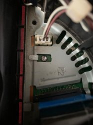
I pulled the white connector instead of trying to pull the ribbon out.. I'm new to this.. I know I'm an idiot. So now I have no way to re solder it. I live in a small asian country and the stores I have gone to tro try and fix it have been no help.. ebay is 120$ shipping for a new motherboard and it's 100$ for a new (used) ps3. I have pictures but I'm not sure how to post them.
Do I try a diy solder? How do you know which Lin goes to which connector?
 
Did you set the picture as your profile picture? If so, the ripped off connector, which the pen is pointing to it, is for the disc tray opened/closed detection switch. If you are not able to find and solder back that part, you've got thease options;
Leave it as is and try loading games from HDD. You can backup your disks using someone's PS3. I recommend this one.

Bridge the connector so the console thinks you never open the disk tray. You need to turn it off every time you want to try another game.
Yes that is exactly the picture I used. Thank you for reaching out. How do I know which two connectors to bridge?
 
25RXVsB
 
Messenger-creation-478-F97-CF-3-E70-49-B3-A2-BD-26-FFBACF66-FB.jpg


Use a multimeter to confirm thease;

1, 3, 4, 6 all connected to GND
2 &5 connected to each other.

If so, you can short 2 or 5 to its neighbor pin. For example, 2 to 1/3 or 5 to 4/6 or even bridge all pins. It doesn't matter.
Let us know about the results, please. Thank you.
 
I will be bring it to
View attachment 44996

Use a multimeter to confirm thease;

1, 3, 4, 6 all connected to GND
2 &5 connected to each other.

If so, you can short 2 or 5 to its neighbor pin. For example, 2 to 1/3 or 5 to 4/6 or even bridge all pins. It doesn't matter.
Let us know about the results, please. Thank you.
I'm going to have to get someone to solder it for me so I just want to make sure I get you completely right.
He should solder pins 1-2-3 in a straight line and then separately solder pins 4-5-6 in a straight line?
Or solder all 6 pins together?
 
Last edited:
If you have soldering equipment you should be able to do this yourself, check the high-resolution pictures on the psdevwiki to confirm the correct orientation.
 
If you have soldering equipment you should be able to do this yourself, check the high-resolution pictures on the psdevwiki to confirm the correct orientation.
Hate to be a bother mate but I have spent a good 3 hours looking at psdev and I can't find anything like what I'm looking for.. do you have a link or can you point me in the right direction
 
Yes that is the correct motherboard. But I am trying to solder a connection so I no longer need the disk tray open/close switch. Which is that the pins numbered 1-6 above are showing.
This picture in the motherboard shows in no way which orientation to solder or bridge the pins to by pass them?

I will be bring it to

I'm going to have to get someone to solder it for me so I just want to make sure I get you completely right.
He should solder pins 1-2-3 in a straight line and then separately solder pins 4-5-6 in a straight line?
Or solder all 6 pins together?
If you could explain this to me a little simpler I'd be happy do my best and share my results I just don't full understand what all I'm soldering together.
Marry Christmas brother
If so, you can short 2 or 5 to its neighbor pin. For example, 2 to 1/3 or 5 to 4/6 or even bridge all pins. It doesn't matter.

Yes that is the correct motherboard. But I am trying to solder a connection so I no longer need the disk tray open/close switch. Which is that the pins numbered 1-6 above are showing.
This picture in the motherboard shows in no way which orientation to solder or bridge the pins to by pass them?
I don't know, because I don't have this machine, and there is no service manual available for this motherboard. Are you trying to bypass its detection mechanism? If so, you can use a multimeter to measure it. Is it 6-pin? This should be easy to confirm.

This is a FFC/FPC flexible cable vertical connector, the pitch should be 0.5mm, and they are easy to obtain.

If I use a multimeter I should have 4 grounds (1,3,4,6) and 2 (2,5) that are connected. After conforming that do I just solder the 2 to the 5 to complete the circuit so the ps3 always thinks the disk tray is closed or do I need to bridge some of the the grounds too like Mr. Dariush said?
 
Last edited by a moderator:
If I use a multimeter I should have 4 grounds (1,3,4,6) and 2 (2,5) that are connected. After conforming that do I just solder the 2 to the 5 to complete the circuit so the ps3 always thinks the disk tray is closed or do I need to bridge some of the the grounds too like Mr. Dariush said?
According to the picture, 2 and 5 are also on the same line, and 1346 is the ground. If this is a closed sensor (please confirm again), connecting 2 or 5 to any ground of 1346 should replace the sensor closed state.
 
1/2 bypass disk tray detection
2/3 bypass disk tray detection
1/2/3 bypass disk tray detection
4/5 small ribbon movement, but no laser or disk spinning
5/6 small ribbon movement, but no laser or disk spinning
4/5/6 ribbon movement, but no laser or disk spinning
1/2/3/4/5/6 bypass disk tray detection
2/5 no activity
This has been a science experiment conducted by me using a broken multimeter and unused solder for connectivity.. if anyone has any reason my results are wrong please let me know.. or else I will be submitting them for peer review
 
You see, 2 and 5 are connected together with a tiny track on the motherboard, which is the detection signal. Switch signals are usually active-low signals, and you can see the surrounding pins(1,3,4,6) are all GND. There are just two signals. The detection signal and GND. so connecting 2 or 5 to GND should mean the tray is closed.
It doesn't matter which one or both. You can also bridge all six pins to each other.
Your test results make sense. Thanks for sharing. Most likely pins 4,5,6 also got damaged when you ripped off the socket, making it not working properly.
 
I soldered all 6 pins together and now it's working great. The playstation has to be completely turned off to change games but that's the only downside so far. The ribbon is moving, the laser is active and so is the Blu ray laser. It is still not reading disks so I will but a laser/disk drive off AliExpress when I have the 11$. I will install it and update again!! Thank you everyone for your help
 
The amount of stress and anxiety I had through solving this simple fix hahah if I can get a laser and disk reader to work I'll ask you about adding another switch later
You can try to fix it completely instead of compromising by adding a switch, you have soldering equipment and the process won't be difficult.

7du4LmG.jpeg

You can get new FPC vertical non-locking connectors with 0.5mm pitch, they are very cheap.
 
Last edited by a moderator:
7du4LmG.jpeg

You can get new FPC vertical non-locking connectors with 0.5mm pitch, they are very cheap.
My level is very low. Me able to fix the disk tray was a very good progress. I think when you see the picture of my solder you would be sad..

My level is very low. Me able to fix the disk tray was a very good progress. I think when you see the picture of my solder you would be sad..
No way I would know what to do with those connectors haha
 

Attachments

  • Messenger_creation_F92995E8-D37C-4E7F-9D31-720582E35DCF.jpeg
    Messenger_creation_F92995E8-D37C-4E7F-9D31-720582E35DCF.jpeg
    137.5 KB · Views: 24
Last edited by a moderator:

Similar threads

Back
Top