Rigol DS1054Z@squeept ...can i ask, what is the make & model of your o-scope?
You are using an out of date browser. It may not display this or other websites correctly.
You should upgrade or use an alternative browser.
You should upgrade or use an alternative browser.
PS3 (Research/Experimental) - NEC/TOKIN Capacitors Replacement - YLOD
- Thread starter Naked_Snake1995
- Start date
Workz_777
Senior Member
Rigol DS1054Z
Oh man, that looks nice. Tsssk, shame about the price tag, better start saving up me pennies then.
Workz_777
Senior Member
Is there any danger in attempting to use 470uf 10V caps? Got 30x of the 10V on accident, like a dummy.
Hiya, sorry i see you asked this twice now. Well, in my opinion, for the short term and for testing if replacing the NECs solves your YLOD, then you could use them. But maybe for long-term use, you might wanna get the Panasonics, 470uF 2.5V ones instead.
I think the RSX & CELL draw (approx) 1.2V - 1.5V (please someone correct me if that's wrong) ...so your 10V rated caps should only provide what the RSX & CELL draw. However, if there was a surge / spike in excess voltage, then the 10V caps can supply all the way up to 10V, but the RSX & CELL probably can only go as high as (approx) 2.5V - 3.3V before damage starts to occurs, so i guess there's the potential danger, excess voltage going to the RSX or CELL. It probably won't happen, but there is a greater risk over a longer period of use, i guess.
Whereas, with the 2.5V capacitors, they can only go that high, so anything beyond 2.5V and they fail, creating an open circuit, and the RSX / CELL never sees anything above 2.5V where potential damage can start to occur. But when capacitors receive alot more voltage than what they are rated for, (say we apply 12V to a 2.5V rated capacitor), then they go 'pop', burn and even catch on fire, see short video clip of that here:-
Regarding the Panasonic tantalums, you can get them from an authorized distributer, like Newark if you live in USA / Asia, or if you live in Europe, etc, then "Newark" is called "Farnell", i would recommend (for the long-term) getting the correct & legitimate tantalum capacitors (for this application) from there. (that is...if your 10V ones do solve the problem once you replaced the NECs with them).
Here is the part number for those Panasonics:- 2R5TPE470M9, they have a very low ESR too. And they have a short height, only 1.8mm high, so they fit nicely under the PS3's metal shields.
You can search that part number here:-
https://www.newark.com/
Or, you can search that same part number on other authorized distributers' websites, like Digi-Key, and as mentioned: Mouser. I personally prefer Newark / Farnell so far, and they also have a cheaper minimum order for free shipping.
Last edited:
Gus21
Member
Hiya, sorry i see you asked this twice now. Well, in my opinion, for the short term and for testing if replacing the NECs solves your YLOD, then you could use them. But maybe for long-term use, you might wanna get the Panasonics, 470uF 2.5V ones instead.
Regarding the Panasonic tantalums, you can get them from an authorized distributer, like Newark if you live in USA / Asia, or if you live in Europe, etc, then "Newark" is called "Farnell", i would recommend (for the long-term) getting the correct & legitimate tantalum capacitors (for this application) from there. (that is...if your 10V ones do solve the problem once you replaced the NECs with them).
. [/ QUOTE]
So which is the best to choose, 2.5v or 6v / 10v?
wrx884
Member
So which is the best to choose, 2.5v or 6v / 10v?
did u even read his reply?? he just told u half a dozen times in that post alone, even went out of his way to explain it.
marciolsf
Member
@squeept i got the cheap scope you suggested (finally!) and after playing with it for a little bit with an audio source, it does look like it works as described! I'm very busy for the next few days, but this coming Sunday I plan on taking my 60gb apart and start measuring things.
Attachments
joe musashi
Member
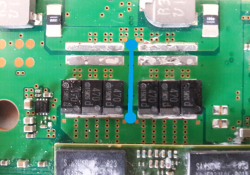
In that image / photo you chose, that is a negative / ground wire. Black = negative (-). You don't need a negative bridge wire. You just need to focus on the positive (+) bridge wire.
So these types of examples (below) are good ones, here the Blue wire = positive (+).
(From Littlebalup, Page 12)
View attachment 25929
Or can be like this also:-
View attachment 25928
Here below, an example of (+) bridge wire on the sides, please note: the wire is black, but it's still being used to bridge (+)
View attachment 25930
EDIT: Also... you can solder the Tantalums first then the wire after, or the other way around, whatever suits you and the shape you did best, these things will come into play when you place the Tantalums on the board to see how to arrange them, then it will become clear to you. It's always harder to work with theory than practise.
you mean i can do as that photo but i mast add bridge wire will that make my ps3 run so good and do you have more photos for tantulim and bridge wire
Attachments
Workz_777
Senior Member
So which is the best to choose, 2.5v or 6v / 10v?
Hiya, Sony put 2.5V NECs on the PS3s, so we are trying to match that voltage, as close as possible.
Some common voltages for "off the shelf" capacitors are like:- 2.5V, 4V, 6.3V, 10V, 16V, 25V, 50V, etc. We must not go lower than what Sony put in (2.5V), but we can go higher...
(a) 2.5V = perfect match.
(b) 4V = next best choice.
(c) 6.3V = no higher than this.
(d) 10V = for testing purposes (if you already purchased them by mistake)
I know this thread is long, 112 pages (and counting lol) but there are so many gems & treasures posted from users, nearly on every page, that if a person read the whole thing - they would come out the other end like a Super Saiyan

Workz_777
Senior Member
@squeept i got the cheap scope you suggested (finally!) and after playing with it for a little bit with an audio source, it does look like it works as described! I'm very busy for the next few days, but this coming Sunday I plan on taking my 60gb apart and start measuring things.
Looking forward to that bro, when you get round to testing on your PS3, if possible could you post some photos of the o-scope measuring the NECs, i'm interested in that model o-scope you just got, and how it compares to squeept's Rigol DS1054Z o-scope NEC results.
Workz_777
Senior Member
you mean i can do as that photo but i mast add bridge wire will that make my ps3 run so good and do you have more photos for tantulim and bridge wire
Well, you can if you want sure, but you can do it any way you like. We just have to work around the limitations.
Originally on your board...
• RSX = 4 x (1200uF) NEC/Tokins = 4800uF.
• CELL= 4 x (1200uF) NEC/Tokins = 4800uF.
Tantalum Replacement Options...
• 3 x 470uF for every NEC removed = 1410uF
• Total per processor is then, (4 x 1410uF) = 5640uF
or if you like...
• 4 x 470uF for every NEC removed = 1880uF
• Total per processor is then, (4 x 1880uF) = 7520uF
The arrangement of the tantalum capacitors on the board (the form / shape) is your choice. They can be arranged in the form of an (X) or (O) or (T) or (Z), etc. It depends on how many capacitors you decided to chose (for every 1 x NEC removed).
Next limitation is, if you removed all the NECs you must add 1 x bridge wire minimum, per processor. But you can add more bridge wires if you like, many people added 2 x bridge wires (in total) per processor. Again, the shape, or arrangment of the bridge wire is up to you, you can be creative.
I highly recommend reading through / scanning the images of this thread. You will see many amazing ideas & information from users who posted their work here. You can either copy them exactly, or be inspired and do similar with some differences. Just keep to the minimum limitations.
Workz_777
Senior Member
did u even read his reply?? he just told u half a dozen times in that post alone, even went out of his way to explain it.
...they didn't even pay me in "likes" lol

joe musashi
Member
Well, you can if you want sure, but you can do it any way you like. We just have to work around the limitations.
Originally on your board...
• RSX = 4 x (1200uF) NEC/Tokins = 4800uF.
• CELL= 4 x (1200uF) NEC/Tokins = 4800uF.
Tantalum Replacement Options...
• 3 x 470uF for every NEC removed = 1410uF
• Total per processor is then, (4 x 1410uF) = 5640uF
or if you like...
• 4 x 470uF for every NEC removed = 1880uF
• Total per processor is then, (4 x 1880uF) = 7520uF
The arrangement of the tantalum capacitors on the board (the form / shape) is your choice. They can be arranged in the form of an (X) or (O) or (T) or (Z), etc. It depends on how many capacitors you decided to chose (for every 1 x NEC removed).
Next limitation is, if you removed all the NECs you must add 1 x bridge wire minimum, per processor. But you can add more bridge wires if you like, many people added 2 x bridge wires (in total) per processor. Again, the shape, or arrangment of the bridge wire is up to you, you can be creative.
I highly recommend reading through / scanning the images of this thread. You will see many amazing ideas & information from users who posted their work here. You can either copy them exactly, or be inspired and do similar with some differences. Just keep to the minimum limitations.
thanks for the help you gave me the hope to fix my ps3 wish i was know about that so early look what i'm going to do i'll put 4 tantalum on every nes with 2 wire but you have not answer me about the wire how much volt i should only use
Workz_777
Senior Member
thanks for the help you gave me the hope to fix my ps3 wish i was know about that so early look what i'm going to do i'll put 4 tantalum on every nes with 2 wire but you have not answer me about the wire how much volt i should only use
Yeah, cause' you haven't paid me in any "likes" yet buddy
")
 (jokes)
As said before, the RSX / CELL processors draw 1.2V - 1.5V (approx) each. So that's how much voltage your bridge wire would be passing. However, you want to go way above that, so the wire doesn't cause any resistance / gets hot / burns.
Many people here used 20 AWG, 18 AWG, or 16 AWG, solid copper core wire, and some people used stranded wire. Any of those gauges you can choose, they are nice & safe for this application.
We go by gauge of wire, AWG (American Wire Gauge), that's how we order our wire, i recommend the 18 AWG soild copper core for you. Get any colour wire you like. Maybe get Red, or White if you like, as those colours are used to indicate it's for positive (+).
Anyways, my missus is asking why i still haven't cut the lawn yet, and i just tell her:- "joe musashi" heheee


Last edited:
nCadeRegal
Senior Member
lol, so I'm not the only one who gets a hard time for how long I'm on here by the other half.......
Workz_777
Senior Member
lol, so I'm not the only one who gets a hard time for how long I'm on here by the other half.......
Hi again..i try to soldering 2 wires to that + and - base on board you shown in first image but completely impossible..because the base is flat and the solder can not fix..i watch a video the man removed the NEC with heat gun very easy and replaced the new on with heat gun again..Hi, what PS3 board do you have? Or what is its serial number?
For the test using external capacitors, you want to leave all the NECs on the board, then you just solder 2 x wires to only one of the NECs, on the RSX.
(See the picture below) Red wire to the (+) Black wire to the (-).
View attachment 25911
Then you can solder these 2 x wires from the RSX NEC to either:- a combination of 2 x 2200uF - 6.3V Electrolytic Capacitors, or to 1 x 4700uF - 6.3V Electrolytic Capacitor, or if you want to some Tantalum Capacitors 10 x 470uF 2.5V, externally (see photo below).
View attachment 25912
Then see if the PS3 boots, if the PS3 does not boot, you could try the same thing on the CELL processor.
what can i do?i just need to solder 2 wires to that pins..
and please tell me what is the specifcation of the NEC TOKAN capacitors?what voltage and what micro farad?
joe musashi
Member
Yeah, cause' you haven't paid me in any "likes" yet buddy
As said before, the RSX / CELL processors draw 1.2V - 1.5V (approx) each. So that's how much voltage your bridge wire would be passing. However, you want to go way above that, so the wire doesn't cause any resistance / gets hot / burns.
Many people here used 20 AWG, 18 AWG, or 16 AWG, solid copper core wire, and some people used stranded wire. Any of those gauges you can choose, they are nice & safe for this application.
We go by gauge of wire, AWG (American Wire Gauge), that's how we order our wire, i recommend the 18 AWG soild copper core for you. Get any colour wire you like. Maybe get Red, or White if you like, as those colours are used to indicate it's for positive (+).
Anyways, my missus is asking why i still haven't cut the lawn yet, and i just tell her:- "joe musashi" heheee
thanks any way about your help and tall your missus i'm sorry to never let you cut the lawn yet i just wait the pandemic to end to buy ever thing
Hi again..i try to soldering 2 wires to that + and - base on board you shown in first image but completely impossible..because the base is flat and the solder can not fix..i watch a video the man removed the NEC with heat gun very easy and replaced the new on with heat gun again..
what can i do?i just need to solder 2 wires to that pins..
and please tell me what is the specifcation of the NEC TOKAN capacitors?what voltage and what micro farad?
can take a photo for your soldering
I had succeed in changing 3 PS3 (backward compatible) NEC tokin (8x) with 470uf (32x) and 6 wires as bridge. But I couldn't repeat the magic with a CHCEH model. The motherboard is smaller and the NEC tokin point is much shorter so I had to remove some solder mask to place in the capacitor. I still couldn't get solve the ylod issue. Any idea apart from NEC tokin, what else could I try out? I already test out (by taking parts from another working unit) power supply, Blu-ray, fan, HDD and still ylod for this unit.
marciolsf
Member
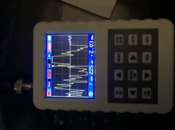
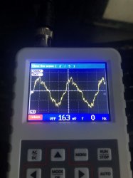
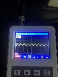
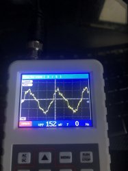
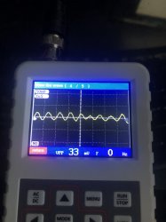
Well, I have the results of my scope! I took two readings for the GPU, and two for the CPU -- one at 50mV/5ms and another at 50mV/1uS. On both pictures, you can see @squeept 's "bad tokin" readings. The funny thing is, i don't have a tokin, it's all tantalum!
I just bought a new set of tips, so this weekend's project is to take them all out, do some readings, test each cap and then put them back on.
I just bought a new set of tips, so this weekend's project is to take them all out, do some readings, test each cap and then put them back on.
Attachments
scope
Scopes! Huzzah!
Hrm..... which model did you end up getting so I can check the sample rate? There have been a couple posted now. I'm thinking these cheap scopes may be smoothing things out too much to tell the difference. Which will, unfortunately, lead me to say: F%$# it, change out your caps 'cause a good 'scope is too expensive.
Do you have a console sitting around that works and hasn't has the caps swapped out so you can compare images?
Last edited:
Similar threads
-
 PS3 Interesting PS3 Errors (1802, 1701, 1601) and Capacitor Replacement
- Started by Cheshire UK
- Replies: 2
-
PS3 CECHA00 with several SYSCON errors (3004, 1001,1002, 2120,3011)
- Started by LSL
- Replies: 7
-
PS3 A0801002 after 4 nec/tokin replacement (maybe Felix or anyone help me)
- Started by Swhalegod
- Replies: 3
-
Hello newcomer to the ps3 modding scene, needing help with syscon diagnostic
- Started by ascendantprime
- Replies: 1