You are using an out of date browser. It may not display this or other websites correctly.
You should upgrade or use an alternative browser.
You should upgrade or use an alternative browser.
PS3 (Research/Experimental) - NEC/TOKIN Capacitors Replacement - YLOD
- Thread starter Naked_Snake1995
- Start date
chugAlugDonna
Forum Noob
Apologies for the LONG backstory, if you don't care, don't read it, and skip to my questions at the end!...I came across this thread only from watching a youtube vid on hot air reflow for YLOD, and the whole nec/tokin cap issue was mentioned in the comments. After reading the first page of this, I was TANTalized to learn of the tantalum caps. I have a CECHH01 that has instant? ylod. It's been dead for yrs, it still has 3.41ofw on it, but I was booting with dongle with hermes cfw3.41. I had it running everything I wanted on it(including GTAV) from 500gb internal hdd and would LOVE to have access to it again. I was originally watching vids to see about a heat gun "reflow" to temporarily revive it in hopes of using data transfer utility to a working slim(CECH-2001A) I acquired that is running 3.55kmeaw[I reallze the old phat would need to be revived and upgraded to 3.55 to do this]. But after seeing this thread, I had hope for the first time of a more "permanent" fix for my old beloved fatty. THEN I remembered I have a BC launch model"A" that is still on 3.40ofw and has been in a box completely tore down for at least a decade waiting for me to try a complete reball as I was always under the impression that was the ultimate problem (also instant? YLOD). It was sent back to Sony many times and NEVER lasted, my only attempt to fix it was reapplying thermal paste on the IHS's only. Didn't work. Replacing the thermal paste on the IHS's DID revive my CECHH01 for a few years when it died the first time long ago, but didn't work the second time it died with YLOD and I shelved it. After reading the first page of this thread(THANKS Naked Snake1995!)I had to fight the urge to buy a bunch of caps and get started, but decided to do the necessary research first. This was really hard for me to do, but I feared removing those damn NEC/TOKINS from everthing I've seen. Before I did anything else, I came across NSC(he's in the place to be) vids and got the confidence to try new paste under the IHS's for the first time. Thanks, NSC! I realized I had yet another fatty(CECHL01) that I tried paste on only the IHS's but has a ~3 sec. delayed YLOD. This one I don't care about, it has newer OFW and was given to me, so I thought I'd try the whole delid thing for the first time on this. Process went "flawlessly" (or at least exactly like NSC's "Best PS3 IHS Removal Video NSC Ever Made" did) but it still has the ~3sec delayed YLOD, nochange. SO, before trying to remove the NEC/Tokins on my beloved CECHH01, I did the delid and mx4 paste on it also. This didn't affect my instant YLOD , still there. I saw no discoloration or other evidence of a bad overheat, or bad paste under the IHS, but I do remember dropping this unit once from waist height onto a hard wood floor that took a chunk out of the floor, but machine worked afterwards, so I "think" no damage to the BGA... I read thru every single page and post of this thread during the last week, and it was a rollercoaster of "hell yeah's!" and "oh $h!ts..", now onto my questions...
RIP-Felix---thanks for your informative posts. How did you come to the decision to use 8 of your recommended caps to replace just one of the NEC/Tokins considering 18 would match the cap and exceed lower ESR of the x4 original NEC's? Just curious. Also, how did you decide which one of the groups of four to replace? Any visual or measurement cues?
Workz_777--any udpates? I forget, what model did you have success with these reimagined NEC/Tokins you created? Was it a BC model, or other?
Anyone--Is the current consensus that replacing some of the OG NEC/TOKINS with only tantalums of proper cap and esr works fine with only the BC models, but for later non BC fatty models you need a mix of proper tantalums AND MLCC's to "replicate" the caps you're replacing?
Thanks again to all the contributors of this awesome, informative, hope inspiring thread.
RIP-Felix
Senior Member
First, good on you for doing your homework before coming to class. Few students do!... After reading the first page of this thread(THANKS Naked Snake1995!)I had to fight the urge to buy a bunch of caps and get started, but decided to do the necessary research first...
RIP-Felix---thanks for your informative posts. How did you come to the decision to use 8 of your recommended caps to replace just one of the NEC/Tokins considering 18 would match the cap and exceed lower ESR of the
Anyone--Is the current consensus that replacing some of the OG NEC/TOKINS with only tantalums of proper cap and esr works fine with only the BC models, but for later non BC fatty models you need a mix of proper tantalums AND MLCC's to "replicate" the caps you're replacing?
Thanks again to all the contributors of this awesome, informative, hope inspiring thread.
I didn't want to remove any more of the NEC/TOKINS than I had to. I replaced with 8x 270µF 2.5v 6mΩ ESR Tant Caps because that's the most that would comfortably fit. I probably could have squeezed 1 more in per rail. So maybe 10, but that's the Max. The main reason I chose to do this is to avoid having to add bridge wires. If I had to remove more, I would have used bridge wires between + rails. I am comfortable allowing the remaining 3 NEC/TOKINs to handle the extra current through their internally connected + Rail, but I personally wouldn't trust just 2 of them. First, it doubles the current passing through them, thus the heat they'll generate will be higher. Second it'll hasten their failure. While I'm not relying on them for capacitance The still contribute to the total ESR. Significant resistance with lots of current = heat, which the PS3 has more than enough of already. And yes, perhaps it would be better to remove them all, use bridge wires, and 18x Caps for a 1:1 replacement. I know that intellectually, but emotionally I chose not to go that far after replacing 1 NEC/TOKIN worked. I didn't want to push my luck..lol!
FYI, feel free to skip the wall of text:
On my first board I was trying to replace with caps and soldering techniques that proved ineffective. So I removed all of the NEC/TOKINs thinking I had to. However, in all cases, I would recommend you only replace as many as are needed. This reduces the chances of scratching a trace, slipping & knocking a component off the board, causing heat stress on the board/flexing/BGA fractures, and etc. Heat stress is the reason I prefer to cut off the NEC/TOKINs instead of working them off with Hot Air. Yes, I recommend using hot air to help solder in the tantalum caps, but that's to achieve a well wetted joint that'll last on the first attempt. That one hit of heat is better than trying to chase down cold solder joints, removing more caps than needed, never knowing if the bonds are at fault or if the BGA is broken, or if the solder will break off even if it did fix the YLOD, and so on. The less work you must do to fix the problem, the better IMO. Delidiong the IHS to replace the TC is a must do (as soon as the fan is audible). If YLOD isn't caused by a HDD failure, Power supply or anything easy, replacing at least 1 NEC/TOKIN is a must do. Reflowing/reballing is the VERY LAST THING to try.
I like to start with the Bottom NEC/TOKINs on the back side of the motherboard, orientated so that you can read "NEC/TOKIN" right side up. This choice is mostly arbitrary, but they are the easiest to get at with my Flush-Cut snips. Also, when using a hot air SMD rework station the backside of the board doesn't "seem" to cause as much thermal stress as does working on the top side right next to the chips - just my opinion.
When Capacitors are in Parallel, which the NEC/TOKINs are, then it doesn't matter which one you remove. There is no easy way to measure them - to confirm if one is bad and only replace it. Note: it might be possible to measure the DC switching voltage noise using certain multimeters or an oscilloscope. I read that this noise should be less than 1mV peak-to-peak. If it's over that, then it would indicate the output filter is not adequate. When the array of them have lost enough capacitance, or the ESR has risen to an unacceptable level, it'll trigger a Boot check error (YLOD). I would be curious if we could find out exactly what the boot check process is measuring. Eg, resistance, capacitance, ESR, ripple current or voltage, et cetera, and exactly where it measures it on the board for both the CELL & RSX. That could be a useful diagnostic value to have displayed onscreen in a hacked console. It might even be turned into a capacitor health meter with a little programming wizardry!
SONY probably used the minimum capacitance necessary, but for decoupling alone going over that amount is okay. There is a remote possibility that the capacitance was arrived at iteratively in the RLC of the second stage filter. RC damps are adjusted iteratively and if there is a reason to do so then the 4800µF total capacitance is significant. However, I doubt there is reason to suspect this matters since processors operate in the GHz range and the resonant frequencies that would apply in this case is 50-100MHz and would probably be decoupled by the ceramics anyway. I myself have gone higher and it doesn't seem to cause any problems. Others here have been using much higher capacitance and it doesn't seem to matter. I only bring it up, because it's not always true that higher capacitance doesn't matter. That's why it's just best practice to replace components with 1:1 parts. A new old stock NEC/TOKIN would be ideal, but it won't last as long as Tanatalum.
Last edited:
chugAlugDonna
Forum Noob
Thanks for the info. RIP-Felix, can't have enough. I REALLY like what Workz_777 did, as I feel a straight jumper cable(if needed) is counter productive to what we're trying to achieve(is that the antikythera device in his avatar or something?). When I finally do attempt this, I'll be building components similar to his. He seems to have come to the conclusion a much higher overall cap was needed for the fix, or at least in his case. I would love to hear back from him, and would love to see how his components will hold up over time. I have concerns of the durability of whatever substrate he used to build his components on(warping, loss of contact over time) and if long term exposure to the heat internally will delaminate his copper tape adhesive and leak goo everywhere...BUT, I think he took the best approach to this that I've seen so far, really impressed! Would also love to see his console analyzed on a O-scope and compared to a machine with all healthy OG NEC/Tokins in place! I might try his method but perhaps build on a thin FR-4 substrate sputtered with copper film. I'll admit I'm really shooting for the stars here, but go big or go home!
I'm still doing homework( I HATES HOMEWORK!!) but since I've waited over a decade to fix my old launch model and have CFW on it, I can wait a ~little longer before getting started, but am dying to. To prevent this I haven't even ordered any parts yet..I've no concerns with the soldering involved except removing those damn crap caps and getting everything clean in the first place. I know that damn board is going to act like a huge heat sink and will make "normal" soldering/desoldering difficult, but don't want to use hot air, am much more comfortable with just a good iron in hand and nonROHS solder.(I HATE using lead free solder).
Is there a safe temp. I can put the whole board in an oven at for a pre-heat (no not a kitchen oven) to facilitate removal and installation that won't cause components to fall off, melt anything, warp anything, ruin other caps, etc? I'm guessing not any that would be helpful...
Off topic, but does this site have anything to do with the old "scene"(psx-scene)? Where did that site go, what happened to it? I joined it back in the early 2000's during the HDloader craze and continued using it until a few years ago I thought?
PanachePanda
Forum Noob
Hey everybody! First off a huge thanks to all those that came before and shared your experiences and knowledge! I've recently been diving in, attempting to fix some of these PS3s and have a few questions.
Is there a valid test for an NEC/Tokin capacitor, that has been removed from the board?
I've been working on a few 'practice' boards, removing them with a preheater/IR lamp, at different temperature profiles. Still trying to nail down reattaching a NEC/Tokin capacitor though. I can't seem to do it with just an soldering iron, so I've been using the same method that I use to extract them, aka the preheater/IR lamp. However I feel like I'm just cooking them at that point, and even if it was good prior, I'm probably destroying it in the process, with that method. I do cover the caps with foil tape, or kapton tape, when using that approach, but still feel like the heat could do enough damage. I do plan on using other tantalum caps, when they arrive, but wanted to test NEC caps from a working board on a non working board.
Chumdiddy1
Member
I'M SO HYPED RIGHT NOW!
I last posted on this topic back on pages 78-79. A summary of my situation after letting my YLOD 60GB sit in my closet completely untouched for a decade. I finally tried to fix it with this method:
First, I popped the bottom side caps off and replaced with 6 caps a piece using the H-shaped wire method I noticed on here.
It didn't work for me.
So I come on here and a user tells me that the yellow Chinese caps I was using were likely not very good due to being cheap and Chinese (lmao). He suggested better caps...and before I could even order them I knock off 4 SMDs! I was SO careful, too. One light slip did it. Three 1005 resistors and a 0603 capacitor. FN TINY PARTS! Flea turds. The 0603 cap is tiny but it looks huge compared to those 1005 resistors. I almost gave up...
...but my PS3 just sat there disassembled and mocking me. Week after week, month after month.
So I order those better caps and try to figure out what values those tiny parts were. I eventually find the schematic online and figure out the values. I then order those replacements.
All of this is done over MONTHS because the world went to sh*t and I'm poor.
I finally get the parts and I hesitate for a bit. My soldering skills and tools just weren't up to snuff. So, I practice on busted electronics once a day and save again to buy a cheap hot air station. The hot air proved invaluable.
Now were back to about a week ago and I dive back in. First, getting those TINY parts back on...slow and hard but eventually a success.
Then today I fit the caps back on. 8 a piece this time. No fancy wire layout, just caps on pads/copper. Boy, it wasn't a pretty job but all were soldered on firmly and cleanly. It looks gross. I wish I took a picture but I decided to test it real quick before even thinking about it. It was gonna fail anyway so the test was just a formality.
I'd have to take it apart again and find the REAL problem after this failed test so I leave the top cover off and only used the most necessary screws in my loose rebuild.
"Is it the chips?! Maybe I actually have a bad CELL/RSX? No way I'm paying for a reball but maybe I can try caps and a reflow? Is it another component"?
*flips power switch while still lost in thought*
Is it a bad power supply? A bad drive? What could it be? Probably bad chips, just my luck.
*tap power button*
It turns on and a second later flashes to the YLO...oh....ohhhhh...
...it's still on? It's still on?! It's putting a signal on to a TV for the first time since 2010!? It still had Fallout New Vegas in it!? It works again!!? It worked. I sat there just looking at it. It still has barely sunk in, haha.
I'm so happy I could cry. It's my first real "win" in soldring/electronics fixing. I've fixed smaller stuff but nothing that tested me like this, nothing I cared about like this. It became my white whale, my Moby Dick...and I caught it. IT FEELS SO GOOD!
Thank you to all that helped here. Truly. I last posted back in March and now I've succeeded. Hopefully it stays working. Tomorrow I'm going to reassemble properly and enjoy my 60GB, $600 baby again LOL. It's still on 3.50, not that it matters anymore.
Thanks again. I'm gonna go to bed now feeling good for once, haha. Go to bed while I'm ahead. Thanks again.
RIP-Felix
Senior Member
I share your concern. Personally I wouldn't trust the durability of any joint not made directly to the motherboard rails. I'm thinking about making a PCB daughter board to mount the Tantalum capacitors to, which can then be soldered to the motherboard, but I'm concerned the shear forces of thermal cycles will break it off (not to mention height clearances).I have concerns of the durability of whatever substrate he used to build his components on(warping, loss of contact over time) and if long term exposure to the heat internally will delaminate his copper tape adhesive and leak goo everywhere...BUT, I think he took the best approach to this that I've seen so far, really impressed!
I ran a simulation using capacitors similar to those @Workz_777 listed. First, I assume these are the 470uF tantalums he used. If so they have an ESR of 25mΩ and a total of 16 of them have a combined ESR of 1.5625mΩ + the combined ESR of the MLCCs he added, which is more complicated math(s) than I care to perform ATM. But it's probably ~4x higher then the NEC/TOKIN array they replaced. Now, KEMET doesn't have an equivalent to add to the sim, but it lets you see what they do in general and how many are needed to lower the combined curve, where they have an effect. We have no idea what the ESR ceiling is. My guess would be under 100mΩ from 100MHz-3.2GHz. But that's based on the CELL/RSX speed and an arbitrary line drawn in a typical use case from this informative webinar. Now, Sony already has an array of 36x 0.1µF MLCCs that are sufficient for the high frequency noise using the NEC/TOKINs to handle the lower frequency noise. If low ESR Tantalum Caps are used, like the ETPSF270M6E caps I linked, which have an ESR profile that stays low into the higher frequencies, I think they'll simulate the NEC/TOKINs pretty well. If higher Capacitance is needed the ETPE330MA9GB have a similar profile, but are 330µF 9mΩ ESR (24x are needed for an ESR of 0.375mΩ). So 7920uF instead of 4860uF. I think the extra MLCCs can be avoided by keeping the ESR in spec with the NEC/TOKINs.
Long story short, perhaps the only reason people have been needing more caps to get their consoles to boot, isn't because they didn't have enough capacitance, but rather it's because they didn't have low enough ESR! Adding caps in parallel lowers the ESR, perhaps to a point where the console will pass the boot check. But again, we don't know what the PS3 is actually measuring (eg, ESR, Capacitance, voltage ripple, etc). That's why I'm so curious. I wonder if that's something that could only be found with source code?
All of this is academic of course. The only way to know is to socket the caps and try different values to experimentally establish the ESR, ripple voltage, and capacitance limits. One could increase the capacitance without changing the ESR to tease out which matters more, and why. Oscilloscopes, vector network analyzers, and open motherboards...OH MY! I'm afraid that's beyond my ability (for now...honorary EE degree, HERE I COME..lol).
I know that damn board is going to act like a huge heat sink and will make "normal" soldering/desoldering difficult, but don't want to use hot air, am much more comfortable with just a good iron in hand and nonROHS solder.(I HATE using lead free solder).
Is there a safe temp. I can put the whole board in an oven at for a pre-heat (no not a kitchen oven) to facilitate removal and installation that won't cause components to fall off, melt anything, warp anything, ruin other caps, etc? I'm guessing not any that would be helpful...
Soldering will be easier if you set your iron temps higher. I don't like to work above 350C because of the potential to destroy copper traces. However, this particular motherboard can probably take the extra heat. You may be able to work hot and quick. I prefer to use hot air (380C) and my iron (350C) in quick strikes to minimize the time at high temperatures.
As for a preheater, this may also help answer @PanachePanda's question...
...I do have a 12"x12" IR preheater. But I haven't tried using it for soldering to the board yet. I attempted a reflow of the RSX using it set it to 180C, but the board only got to 97C as measured with an IR thermometer. As the heat approached 240C the board began to warp (along with poping/creeking sounds...cringe)! Perhaps the preheater wasn't hot enough, I'm thinking that's the case. Regardless, a preheater would surely help with soldering, but could warp the board if not secured into a motherboard jig for support. This weekend I made a jig out of 1/4" Aluminum sheet metal. It still needs more work, but I'll be using it to keep the board from warping in the IR preheater while using Hot air for an upcoming reball attempt. The reballing templates, jig, and solder balls arrive from china in a month or so. Gives me plenty of time to get the support jig right. This is mainly for my own education working with electronics, I doubt it will resurrect PS3 #1. I'm fully expecting to find lifted BGA pads, but it's an avenue forward and that gives me hope.Hey everybody! First off a huge thanks to all those that came before and shared your experiences and knowledge! I've recently been diving in, attempting to fix some of these PS3s and have a few questions.
Is there a valid test for an NEC/Tokin capacitor, that has been removed from the board?
I've been working on a few 'practice' boards, removing them with a preheater/IR lamp, at different temperature profiles. Still trying to nail down reattaching a NEC/Tokin capacitor though. I can't seem to do it with just an soldering iron, so I've been using the same method that I use to extract them, aka the preheater/IR lamp. However I feel like I'm just cooking them at that point, and even if it was good prior, I'm probably destroying it in the process, with that method. I do cover the caps with foil tape, or kapton tape, when using that approach, but still feel like the heat could do enough damage. I do plan on using other tantalum caps, when they arrive, but wanted to test NEC caps from a working board on a non working board.
@PanachePanda You won't be able to reattach a NEC/TOKIN with a soldering iron. To attach a NEC/TOKIN, you'll need hot air, which could warp the board and break the BGA under the chips (I'm speaking from experience unfortunately).
Chumdiddy1
Member
Yes, these phat PS3 boards are just massive heatsinks. It's easily the hardest to solder to that I've ever faced in that regard. Without hot air it just wouldn't have been possible on my end as I don't have a really thick soldering tip for either of my irons. Soldering to the pads is easy enough but I took off some mask to solder straight caps to pad and exposed copper. The exposed copper areas just didn't melt with an iron. Hardly at all. When it did I didn't trust the joint and usually found it to be an incomplete bonding.
I may be a moron for doing it but I insulated the board when working these final time so it wouldn't cool too fast and noticed a difference. Air on 350 was enough to get things moving on the exposed areas.
Finally, if you have removed the IHS you can remove the Tokins. Just go slow. It was one of the first things I had ever done on a board and out of everything I did to fix it, the Tokins I removed was by far the easiest part. Just go slow.
Yugonibblit
PSX-Place Supporter
This was interesting to read, but I have fixed many consoles with this tut, but sounds correct if your RSX OR CPU are lifting off the motherboard from bad solder joints. NEC/TOKINS do go bad so sadly this is not mentioned in this info . https://ps3specialist.com/blog/the-...placing-the-nectokens-by-tantalum-capacitors/
PanachePanda
Forum Noob
As for a preheater, this may also help answer @PanachePanda's question...
...I do have a 12"x12" IR preheater. But I haven't tried using it for soldering to the board yet. I attempted a reflow of the RSX using it set it to 180C, but the board only got to 97C as measured with an IR thermometer. As the heat approached 240C the board began to warp (along with poping/creeking sounds...cringe)! Perhaps the preheater wasn't hot enough, I'm thinking that's the case. Regardless, a preheater would surely help with soldering, but could warp the board if not secured into a motherboard jig for support. This weekend I made a jig out of 1/4" Aluminum sheet metal. It still needs more work, but I'll be using it to keep the board from warping in the IR preheater while using Hot air for an upcoming reball attempt. The reballing templates, jig, and solder balls arrive from china in a month or so. Gives me plenty of time to get the support jig right. This is mainly for my own education working with electronics, I doubt it will resurrect PS3 #1. I'm fully expecting to find lifted BGA pads, but it's an avenue forward and that gives me hope.
@PanachePanda You won't be able to reattach a NEC/TOKIN with a soldering iron. To attach a NEC/TOKIN, you'll need hot air, which could warp the board and break the BGA under the chips (I'm speaking from experience unfortunately).
@RIP-Felix Do you have a lamp with the preheater? I find that is key for targeting specific areas and bringing them up to temperature, instead of getting the whole board hot enough to flow the solder again. When removing the capacitors, I'm running a profile of 90C for the preheater on the board, and run a heat profile for the IR lamp that slowly brings it up to a target temperature, in my case 230C, then ramps it back down. That makes removal so easy and clean.
As for reattaching the original NEC/TOKINs, I've tried using a similar method. I clean my pads, lay some flux, then position the caps in place. Also, I should mention I put heat foil tape over the caps prior, to protect from the direct lamp heat. After in position, I run a similar heat profile to when I'm removing them. In a few cases, I've gotten them mounted what looks to be great. However, I'm wondering if that heat, even though covered, is still damaging the caps anyway?
I was just curious if anyone had a clever way, that I didn't think of, to reattaching those TOKIN caps. Which is probably a silly move on my part anyway.
Chumdiddy1
Member
This was interesting to read, but I have fixed many consoles with this tut, but sounds correct if your RSX OR CPU are lifting off the motherboard from bad solder joints. NEC/TOKINS do go bad so sadly this is not mentioned in this info . https://ps3specialist.com/blog/the-...placing-the-nectokens-by-tantalum-capacitors/
I'm aware of that repair service/person and I've heard some interesting things about them. I'll leave it there.
That said, their post sounds like a person losing a lot of business. Honestly. I never did but almost used his services so I have no reason to speak this way out of spite or anger. Just reading that sounds like a person that's bothered by lost business.
His claim that every repair looks awful is absolutely wrong. Sure, some do but if it works it works.
His claim that a person has to buy a soldering iron, flux, solder, caps, etc is true. However, all of that is STILL cheaper than his reball services. Also, it can teach you skills for the future as well as a hobby.
I know that the cap replacement offers it's own problems for many. Some games behave differently and such but I think it has proven beyond a shadow of a doubt that the main issue IS NOT the solder balls under the chips but bad capacitors.
Heck, the exact same Tokins were so bad that they're partially what caused this method to be found in the first place! Electronics repairmen have been fixing these things in Toshiba laptops for a while now. In fact, looking back it's stunning that nobody put this together sooner! All the "pros" offering reflow and reballs never looked at the 8 giant caps known for failing all the time? Ever? Haha, ok. Strange.
I don't want to debate what is the best fix as each console has it's own issues. Sometimes a reball IS the fix but it was sold as THE ONLY fix for years and we now know it isn't true.
I mean, taking off the Tokins and adding 100 tantalums won't get a PS3 with a bad chip or solder balls to start. So...why are so many fixing their consoles with these cap replacements?!
Finally, he asks how heating the cap could possibly get them to work again - as if that's crazy - when we know that's exactly what happens with many caps. Heating will get them to work again for a bit...but only a bit. Hence the temporary fix of reflow and reball when not needed.
It all reads like a guy losing business to me.
marciolsf
Member
I'm aware of that repair service/person and I've heard some interesting things about them. I'll leave it there.
Asides from the debate on "will it/won't it", what have you heard? I'm thinking on sending my board there for a reball, mostly because I want to rule that possible issue out . I've already gone through two separate sets of tantalums, and based on the discussion in the syscon thread, the current thinking is that either the solder balls or the rsx have gone bad...
RIP-Felix
Senior Member
I'm not super keen on IR lamps, as they perform differently depending on the surface (IR reflectivness). Hot air provides more consistent heat, but you can't trust the setting and need to measure the temp to get it set right.Do you have a lamp with the preheater?
My preheater is just is a simple bottom preheater. I only used it once to get the board to 97C, but was shooting for between 150C and 180C, over a 5 minute period. I would never preheat the board higher, as then the components would start to fall off as the solder melts. No, it's just to decrease the temperature differential between the topside heat (from heat gun on component I want to remove) and bottom side. The smaller the temp. difference the less the warping. I wasn't going to spend $200-$500 on a proper BGA rework station just for this project, and I'm not running a shop, so no real point. The preheater will come in handy on other projects, so I pulled the trigger on it. Problem is that it only came with 10A cord on a 15A device, and it was HOT! So I just replace the cord with a 15A rated one and will try getting the board hotter next time.
For the reball, I just got a temp meter with 2x K series temperature probes so I can get more accurate readings on the board near the chips. And the Jig is for insurance against warping.
Now about the heat damage from installing components. They are designed to withstand reflow once during assembly without affecting their rated performance. Typically I've seen data sheets say 240C for 30s to 1 minute in a reflow oven. The more times they undergo that intense heat, the sooner they'll die. I wouldn't worry about killing the component unless you have been heating it up for longer than 30s at 240C many times. If you buy new old stock NEC/TOKINS, then you should be able to use a preheater and Hot air to install them fairly easily. You could try solder paste, as that's whats used to install them initially anyway. Lead solder will work at lower temp and give better elasticity to the joint.
Note, the internal component temperature is not the same as the hot air or iron setting. You may be working with 380C hot air and a 350C iron, but it takes that much heat to bring the temperature of the board and component up to the melting point of the solder (217C for SAC lead free). The component itself probably isn't getting much hotter because once it reaches the melting point you remove the heat. Now, sometimes solder can be oxidized (hard and brittle, won't melt, acts like glue). That's what flux is for, it reduces metal oxides and allows the solder to flow again. You need ample flux, and sometimes to reapply mid way when you notice it all dry up, to get the part to come off when it get's up to temp (at high temp, metal oxides form quickly). This is why you probe to check if it's moving & and add more add flux, so you don't keep the heat on it for too long after it has already melted, because then you're just heating it up more than necessary and for longer than necessary. That will shorten the life of the component.
My rule for well wetted joints at 350C is not to hold the iron in place for longer than 3 seconds. In that time, If I couldn't get the solder to flow like water and the heat to penetrate the pad (like the PS3 motherboard will to do you), the I add hot air to preheat the area until 3 seconds works.
The reason is to prevent metal oxides from weakening the joint and also to allow the component's thermal mass and specific heat capacity to limit the amount it's temperature can increase. Sorry, physics terms, basically it's like juggling a hot coal from hand to hand. Yes it's 2000 degrees (Hot AF), but it can't transfer that heat fast enough to burn you if you only hold on to it for a second or two. Remember, the higher the temperature the faster metal oxides form- hard nasty solder blob that won't melt and breaks easily. You can see this happen. Oxidized solder has that matt greyish finish and a good durable joint will have a silvery mirror shine. Flux helps greatly, as do fast strikes (no more than 3s). At 240C in a reflow oven 30s might be fine as it takes longer for metal oxides to form at lower temperatures. Ideally all soldering and reflowing would be performed using an inert gas (like Nitrogen) to shield the weld. Oxygen is the enemy here, but that's too hard to accomplish and not necessary as your soldering technique improves.
niino
Member
Did anyone already try using SP-Caps? They are probably the closest thing to a Proadlizer you can get nowadays. They are similarily constructed ultra low ESR polymer aluminium caps with high ripple capability designed for use in CPU/GPU VRMs, just like the Proadlizer. I am planning on using 4 of these for each 1200µF Proadlizer in a CECHC. However, space might be an issue, since these might be very thin (1.9mm, even less than the Proadlizer), but 7.3x4.3 in area. Is this a good or a bad idea? I am not really comfortable with replacing the Proadlizers with tantalum caps, which behave completely different, and SP-Caps are basically the same thing as the Proadlizer once was.
chugAlugDonna
Forum Noob
Ok, so i usally dont comment on the whole NEC tokin issues. So here goes...
I've been repairing a lot of PS3 FAT models recently
The NEC tokin defects has been known for a while and was heavly reported when toshiba had to recall alot of laptops to replace them.
So to diagnose them, a oscillscope or removed from the board is the only way to truely find out whats wrong with them.
A fresh new NEC tokin will read about 2000uf capacitance, overtime this will drop and most boards i diagnose they tend to drop to 1300 - 1200uf - This is still enough for the PS3 to work at full load without causing the YLOD.
Boards that have had nec tokin fails tend to show runtime issues rather than boot up issues.
So to the point, the whole nec tokins issue is one of many issues that cause the PS3 boards to have a YLOD - its not the one and only issue. And from my repairing these is the 1 in 10 of problems.
So I will list the issue i spend most of the time repairing:
So, how do you diagnose these issues?
- 80% - Dry solder under the RSX, breaking contact causing YLOD issues
- 10% - Dried thermal paste causing overheat alerts
- 4% - Dead RSX or CELL - mostly down to heat frying them - sony's fan policy is insane and allows the cell and rsx to go to 85C
- 2% - Broken Blue ray drives - controller fails, laser lens break
- 2% - Short circuits - SMD capacitors going short circuit
- 1% - Dead southbridge - Very rare but they do fail
- 1% - Other odd ball issues and simple fixes, nec tokins
Well simple steps, and logical steps will identify the cause of your YLOD - I suggest some diagnose process before attempting any nec tokin replacement as 9 out 10 times results in further breakage!
Tools are the important part of this process - Good multimeter, tweezers, solder paste, flux, thermal paste, schematics, basic component removal hot air gun, IR BGA preheater is a must.
And patience!!
Step 1. is easily diagnosed, you can apply pressure to the bottom and turn on, if there is no ylod then thats the issue - dry joints
Step 2. After being on for a less than a minute the fan will spin up fast and overheat issue will show up on screen - if you are on the cfw you can see the what temps are shown and identify the CELL or RSX.
Step3. This one is interesting and a basic resistance check can be used to identify:
So the CELL and RSX on the nec tokins pins will give a resistance level on the ground and postive pins:
CELL - 5.0, 3.3ohms down to 2.2ohms, if 0.2 ohms then most likely dead cell
RSX - 4.4 ohms down to 1.1ohms again 0.4 or lower dead im afraid
This logic can be applied to the other IC's, this is nothing new and basic electronics but a must to diagnose issues.
I would use this logic on boards that i have no schematics.
A big problem i have is getting parts, so i spend alot of time removing parts from donor boards.
I hope this helps this thread in its approach to this issue and not blindly going in a taking off nec tokins without thinking what could be the issue?
I still have concerns over needing reball, as I have fast ylod and heating caps still won't allow booting. I partially disassembled, then attempted booting whilst pressing HARD over cell, then rsx, still fast ylod either way. SO, finally removed both pairs of caps under emi shield(opposite side of actual rsx and cell) and tested resistance between gnd and power rails. Cell side measured 4.42 ohms. RSX side measured 2.38 ohms. Can I rule out dead cell or rsx now? Then went ahead and tested capacitance(I think, maybe used diode drop setting?) between power rails on rsx and cell. Between power rails on cell side, one group measured ~.307nF,then flashed mF, then ended on open(OL). Other group measured ~1.89nF, then ended on open. RSX 1st pair measured ~.19nf, ending on open. Second pair measured ~.17nF, ending on open...Does this tell you anything?
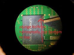
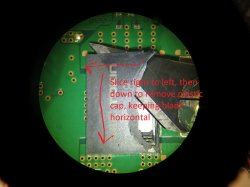
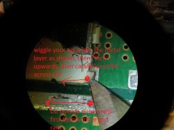
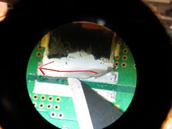
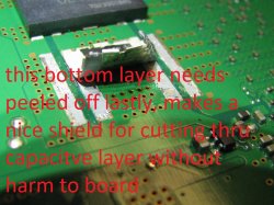
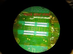
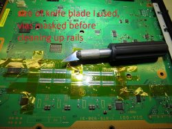
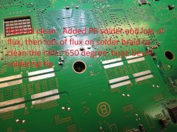
Finally decided to remove both pairs of nec/tokins from top? of board(under emi shield, not side of actual rsx, cell chips). It was surprisingly easy to do with a large hobby knife and steady hands AND after reading thru everone's tips and tricks here. Surprisingly I found one thing I DO like about the ROHS solder...It was so much harder than leaded solder(obviously) and you could get your blade under the long pcs on the gnd and power rails and "flick" the ends up, then work your blade across and peel them completely off the solder easily without any heat involved. It literally took less than a minute per cap, no heat, no damage whatsoever. I'll try to upload some pics I took along the way to help the tentative visualize what people have been trying to explain...Since it was easy to remove the long pcs of metal actually left behind on the solder rails without heat, it was pretty easy to clean up. I added some Pb solder to the rails, then LOTS of flux, and LOTS of flux on pcs or solder braid and a large bevel tip @650degrees to clean the rails up. My goodness, that board can take some heat...But worked in my favor as there was no sign of lifting or damaging the rails during the process. I would normally never use the temps and time I used to clean them up, but the board took it like a trooper. Thanks for everyone's tips and tricks mentioned throughout this thread.
Attachments
Last edited by a moderator:
Chumdiddy1
Member
Asides from the debate on "will it/won't it", what have you heard? I'm thinking on sending my board there for a reball, mostly because I want to rule that possible issue out . I've already gone through two separate sets of tantalums, and based on the discussion in the syscon thread, the current thinking is that either the solder balls or the rsx have gone bad...
I don't mean to spread lies or rumor but many have claimed to send their console in only to have him claim it can't be fixed and offer a tiny amount of money for it.
Further, some claim to have marked their console and/or parts in different ways and definitely didn't get their original parts back *in devices he made that above claim about*. Implication being he will swap your good components for bad before sending it back if you decline his cash offer.
Some had pictures to prove this.
Also the many that claimed he didn't even reball but reflow their systems on top of those that said the PS3 broke again in a couple weeks.
Again, it's just what I heard.
RIP-Felix
Senior Member
The reason I lile the tantalums capaictors more is because the have better ESR performance into the higher frequencies. You'll see what I'm talking about if you enter the part numbers for yours caps (EEFGX0E331R ) and mine (ETPSF270M6E) into panasonic's part sim. I will admit that 3mΩ ESR is pretty sweet, but I suspect there is a good reason SONY and others are using tanatalum caps in their filters now. Why would they use the more expensive and geopolitically problematic tantalum if they could avoid it? You could try them and see.Did anyone already try using SP-Caps? They are probably the closest thing to a Proadlizer you can get nowadays. They are similarily constructed ultra low ESR polymer aluminium caps with high ripple capability designed for use in CPU/GPU VRMs, just like the Proadlizer. I am planning on using 4 of these for each 1200µF Proadlizer in a CECHC. However, space might be an issue, since these might be very thin (1.9mm, even less than the Proadlizer), but 7.3x4.3 in area. Is this a good or a bad idea? I am not really comfortable with replacing the Proadlizers with tantalum caps, which behave completely different, and SP-Caps are basically the same thing as the Proadlizer once was.
Yes, these rails are uber durable compared to most boards I've worked on. I assume you mean 650 degrees Fahrenheit, because it converts to about 340C (a good safe temp to use). I like to use flush cuts to get the caps off, only takes minutes. 350C with a T12-C4 tip and I dip the braid into rosin paste flux to clean the pads. Works great!...Cell side measured 4.42 ohms. RSX side measured 2.38 ohms. Can I rule out dead cell or rsx now? Then went ahead and tested capacitance(I think, maybe used diode drop setting?) between power rails on rsx and cell. Between power rails on cell side, one group measured ~.307nF,then flashed mF, then ended on open(OL). Other group measured ~1.89nF, then ended on open. RSX 1st pair measured ~.19nf, ending on open. Second pair measured ~.17nF, ending on open...Does this tell you anything?
...I added some Pb solder to the rails, then LOTS of flux, and LOTS of flux on pcs or solder braid and a large bevel tip @650degrees to clean the rails up. My goodness, that board can take some heat...But worked in my favor as there was no sign of lifting or damaging the rails during the process. I would normally never use the temps and time I used to clean them up, but the board took it like a trooper. Thanks for everyone's tips and tricks mentioned throughout this thread.
That resistance seems okay to me. I haven't seen a resistance as high as 4.43Ohms, but meters can be different and it's in the ballpark. Unless you take the cap out of circuit you can't get reliable capacitance readings, and the heat from removing them intact would change their capacitance. So yeah, those numbers are meaningless and don't prove the CPU/RSX are fine. I HIGHLY doubt you'll need a reball, but until you install the caps and test, there's no way to know for sure.
Have you decide on caps and bridging method yet?
marciolsf
Member
Yeah, that's fair, thanks. I've only done some light research, I better do some more before I make my mind up.I don't mean to spread lies or rumor but many have claimed to send their console in only to have him claim it can't be fixed and offer a tiny amount of money for it.
Further, some claim to have marked their console and/or parts in different ways and definitely didn't get their original parts back *in devices he made that above claim about*. Implication being he will swap your good components for bad before sending it back if you decline his cash offer.
Some had pictures to prove this.
Also the many that claimed he didn't even reball but reflow their systems on top of those that said the PS3 broke again in a couple weeks.
Again, it's just what I heard.
he also has a page on his site complaining about users on ripoffreport.com saying he kept this consoles and money.Yeah, that's fair, thanks. I've only done some light research, I better do some more before I make my mind up.
Similar threads
-
 PS3 Interesting PS3 Errors (1802, 1701, 1601) and Capacitor Replacement
- Started by Cheshire UK
- Replies: 2
-
PS3 CECHA00 with several SYSCON errors (3004, 1001,1002, 2120,3011)
- Started by LSL
- Replies: 7
-
PS3 A0801002 after 4 nec/tokin replacement (maybe Felix or anyone help me)
- Started by Swhalegod
- Replies: 3
-
Hello newcomer to the ps3 modding scene, needing help with syscon diagnostic
- Started by ascendantprime
- Replies: 1