I write this in addition to main guide (work in progress) by db260179
https://www.psx-place.com/threads/f...syscon-first-steps-and-error-reporting.30100/
I will try explain step by step, as easy as I can explain it.
Really this can be done in 10 minutes.
First of all let's make clear what we are doing:
We are simply running a python script that will let us communicate with the PS3 SYSCON, using a serial (COM) port.
We can thank guys like 'Major' and 'zecoxao' for making this possible in the first place. We are just running their script.
So, what do we need in order to run this script?
Python 2.7.18, with additional modules pycryptodome and pyserial
For Windows users (most people) this is what you can do:
-First install python 2.7.18 (get from python.org)
-When you run the installer, you can check the last box (it will make things easier; lets you run python commands from any location)
Once it's installed, you should already be able to run python commands and scripts. How? Directly from the windows command prompt, you can type: python script.py
But our particular script relies on two additional modules. (If you try without them, it will tell you the problem)
But don't worry,
You can download and install them automatically by typing:
pip install pycryptodome
pip install pyserial
That's it. Now you should be able to run the magic script. Just specify the COM port and the syscon mode at the end.
For example:
python uart_script.py COM4 CXR
What COM port?
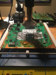
This is where the USB to serial 3.3v adapter comes in handy.
When you plug it into your computer, it should show up in device manager as a COM port. If not, you need to install drivers for it.
This will depend on your particular computer and dongle.
What is CXR? This will depend on the syscon you are trying to communicate with. SW is for newer (SherWood) Syscons. CXR(F) for the older BGA models
Further details in the PDF
If all is correct, no errors will come up immediately. Even without any cables connected.
You can then type AUTH, and will get
"Auth1 response invalid"
Of course, to get past this, everything has to be connected properly. Even then it may take a couple tries in a row. Eventually you should get:
Auth successful
(If you are still getting "Auth1 response invalid, first simply try again a couple times, turn the ps3 power off and on, if not, swap Rx and Tx wire around and repeat. Check the connections etc... It should work in the end)
That's it for now