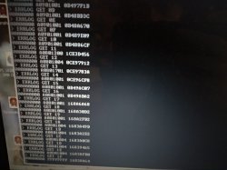
Actually it's 32. It was always up to 32 errors. We thought it was 20 in external mode because we were just counting wrong. Instead of 00 to 19 is 00 to 1F haha.
I just went and counted them, yup it's 32. Still, it fills up quick and tells the error history of the console, so it's important to back that up before generating more codes.
And people please hold your horses there with the reflows... We can complain all we want about the fake tokin fixes but reflow isn't necessarily repair either. It can be similar fake result but even more destructive.
Yes, sometimes it's just a BGA defect under the RSX. This is why reballing is the valid step forward once you find RSX problems. If and when it fails again, then you will know if your problem was actually on top, and not under the chip.
But "reflow" alone will not help you isolate the problem any further. The thing will be destroyed beyond repair in the end and you still will not be sure why. This is not what we are here for. Might as well do the hairdryer trick or whatever.
Only reballing can guarantee good BGA without the oxidized pads that will never be wetted by just reflow. Just that. It's not magic either, but Nobody would do reballing if it were stupid, considering how difficult it is.
Your choice after all. Things are never so simple.
Ahh! The reflow police!
First, not all reflows are equal. Our estimate of 1year is based on heatgun specials, not a proper reflow. My ghetto setup isn't a proper setup either, but it's better than a heatgun. Escpecially if you thoroughly clean out the dirt, grime, flux residue, and dust that has accumulated under the BGA first. But the biggest factor is the activation time above 150C with flux. Flux is a reducer (opposite of oxidizer), it reduces the oxidation on the old solder balls and pads. It needs a little time to do this, less when hot. So 3 minutes at 150C + a few more getting up to 180 before the reflow is going to help alot...
Except it doesn't benefit from abrasion (scrubbing) you get from multiple cleaning passes with fresh solder and braid. And the solder is old lead free, which is not as good as new leaded. So of course reballing will yield longer lasting results.
@Pacorretaco is correct. A reflow is not as good as as reballing. And even reballing isn't 100%. Reballing doesn't renew the Die or RAM bumps. It doesn't affect the VRM or TOKINs. It doesn't fix blown fuses or shoring caps. You still have to perform proper diagnosis first.
I just rewatched this last night and was impressed with its accuracy...
While it sounds like he's endorsing the tokin fix, if you pay close attention he's really saying we shouldn't latch onto any one repair. When asked about the error, Sony themselves said that the YLOD was a "general error" that needed to be "diagnosed" before the problem can be identified. With what we know now, finally having access to the SYSCON, which SONY had all along, they were absolutely being honest. That's the best way to describe a YLOD. But people didn't want to accept that!
After watching this I read through the comments section and people were going the other way...
'Reballing's a con, and it was the tokins all along...haha!'
They completely lost the point and went 180-degrees to the opposite extreem! I think it say's more about an innate human desire for irreducibly complex problems to reduce to easy solutions...which of course they can't. I guess we latching onto the first explanation that looks easy (tantalum, which aren't! They just look easy.), or places blame on someone else (lead free solder cracks). One easily accepted explanation is a manufacturing defect that places blame on SONY and they should refund us. The other seems to place the fix within our ability and price range. These are perceptions, narratives that enable our EGO, but have little bearing on reality. We will believe anything that seems possable, to avoid admitting to ourselves we're to blame or incompetent.
The truith is that the YLOD is a general hardware failure. You need to diagnose the issue before you can attempt a fix. And that it is a futile effort in the long run anyway, because FC BGA technology is unreliable. Heat cycles will cause a BGA defect eventually. There is no strain relief! The solution is simple. PGA and sockets for hot running chips. That's how PC's have done it for years.
So why are laptops, tablets, and video game consoles stil FCBGA? Planed obsolescence and greed? Maybe that's the answer my ego wants me to latch onto, but it's probably more that they wanted to balance cost and reliability to pay their employees, sharholders, and executives a competitive wage. To remain competitive in the console video game space, which is cut throat to begin with. From that perspective, can you really Blame SONY?
YES! Yes you can! Consumer electronics should not have FCBGA CPU, GPU, or APU's ever! They should all be socketed for reliability. It is a more expensive process, but consumers would gladly pay extra for the option and the only reason not to give them one is greed.