It has been a long time since I revisited this console. If you don't recall, you can follow the link above to see what I last did. But the short versions is that it had errors A0403034/A0404002. This COK-001 MB has a 202GB SYSCON. So it does record an associated Data Error with the 3034. I attempted a reball on this console, which failed. I later attempted to Frankenstein mod it. Board had 3/4 more heating cycles to attach a 40nm RSX, which failed. At this point there were 2 torn RSX traces and some missing pads. The missing pads appeared to be N/C. Trace damage repaired using Wylie lugs.
Just a little background on my Ghetto Reballing setup. I use 2 thermocouples, cheap k-type in a flex tube magnet thingy. They're just stuck on the side of my T8280 with a binder clip. One sticks up from below the RSX to get bottom motherboard temps. The other I place next to the edge of RSX on topside…
I put aluminum tape around to outside to keep heat in better and prevent drafting. For top heat I use a cheap hot air wand with the fan built into the handle. They're all pretty much the same.
When I did this board, I was still baking the boards for 2 hours on the T8280 at 100C, before starting any BGA rework. I have since started baking the boards for 24 hours and then sealing in anti-static bags with desiccant packs, until I'm ready to work on them. This is because I've run into boards that have too much moisture to bake out in 2 hours. Motherboards from humid climates like the southeast US, Hawaii, and Japan.
However, most of the boards I get don't have that much moisture and a 2 hour bake is all that's needed. I can usually tell if the board needs more baking because the thermocouple on the topside and bottom side will read within 5-10C of each other. The more moisture the larger the difference. It only works if I wrap the MB up like a baked potato to reflect the IR radiation (heat) back down and keep it in.
If I didn't do this, there will be a much larger top/bottom side temp difference. The difference in the thermal expansion rates between top/bottom layers of the MB causes it to curl (which I call tacoing). To prevent tacoing I clamp the MB into a jig to keep it strait, but the larger that temperature difference, the more shear stress there is on the internal layers. This makes it more likely to delaminate or break internal traces. So that's why I wrap the board up like this.
Anyway, while prepping the motherboard for the 65nm RSX, I realized I had previously used it as a donor. This is my second MB ever. One I thought I had irreparably destroyed while learning to reball and following bad advice. So I had already written it off and started harvesting from it's corpse. So it was missing some important 10k resistors I needed for other Frankies. Also, R1014 by the CPU I used too. If I didn't replace those this attempt won't get far! But first the 65nm RSX needed to go on…
The 65nm attach went well and the ohms tests looked good! So at least there's no short (on the RSX – forshadowing) that renders the attempt dead on the spot. So there's a chance!
After cooling I cleaned the MB thoroughly and I left the 18x 270uF B-Case Tants and bridge wires in place. But added 4x 470uF AlPol. For now at least. I repopulated all the resistors I harvested for other boards. Then I wrote the SYSCON training data to enable the 65nm RSX. Time for a Test!
1.5s YLOD with SYSCON error code A0022110. Usually a 2110 is F6001 or PS6001, but they checked out. I checked all the other fuses looking for open lines. They all had continuity. Checked voltage lines looking for shorts, but none were short to ground. 3.3v_MK_VDD was only reading 1.5v, but I couldn't tell if it didn't get a chance to rise before the power cut, or the power cut because it didn't rise to 3.3v. I didn't think IC6020 would output 1.5v at all if it were bad. So I leaned toward the former.
I was stuck at this point. I started scouring the MB looking for missing components I might have harvested and forgot about, or that might have popped off. I found some differences between my MB and another COK-001…
My board:
Another board:
What's weird is that I don't remember harvesting from this area. I suppose it's possible, but I have no memory doing so. I looked up those parts and...no, they are supposed to be unpopulated. However, 2 other boards I had laying around do have them populated. Apparently there are differences like this between motherboards of the same revision. One COK-001 board might have them, another might not. That makes finding missing components by comparing to another MB confusing! Be warned!
According to the service manual they form a section called "PLL select," which I guess is not used on my particular board. But for some reason the resistors are there on some boards. I don't get it. It was just an oddity I ran into.
That's when I decided to replace IC6020, a DC/DC converter that forms 3.3v_MK_VDD for the clock synthesizers. It didn't work, same 2110 error.
I was licked at this point. I'd run out of ideas and decided to set it aside until I felt the itch to return to it or found something that could move the needle forward. I moved onto another console, collated more data from the SYSCON thread, really dove deep into finishing the PS3 YLOD documentary…basically I became so engrossed in other projects and forgot about everything I had done to PS3 #2 up to this point. It all got jumbled up and I couldn't keep it all strait.
Later I got an idea and attempted to replace IC5001 (clock synthesizer). No change. But during this round of tests I noticed low resistance on 3.3v_Misc line. It was getting 41 ohms to ground. I tried removing Q6001, C6029, C6031, and C6034. All the 3.3v components on Side A of the MB except L6004, which I'm fairly certain can't be causing it. None of them removed the short. So I put them back. That's bad Cuz now the short can be literally anything down stream. Which is a lot!
The only path forward I could think of was to try injecting voltage and see what get's hot. At the time I didn't have a thermal camera and the only way to do it was to try spraying with IPA and see what evaporates faster. Very difficult and unreliable method in my experience. I tried it but couldn't see anything. And nothing on the circuit took an unreasonable amount of amps. So, I didn't think there was a short.
That's when I noticed R6016 was missing. It's a 47k. That's a value I might have used for a Franky.
So, I replaced it and tested the console. No change. Still 2110. This had become a full blown Ninja Gremlin and was taunting me at every stage!
Then I noticed resistors missing from IC6200. Must have been knocked off during tokin removal or Tantalum install. Wasn't it either. Ninja Gremlin strikes again!
The board sat for a long time. Then @DeadEnd had a board with the same error and had been doing lots of tests and troubleshooting. He suggested I check IC6204. I now have a Flir thermal camera and decided to try it out, sure enough IC6204 was getting hot (short) as he said.
Replaced it and the 3.3v_MISC short disappeared! Love that thing (Flir themal cam)! Thanks @Computer Booter. Thanks @DeadEnd!
I have previously found that R6016 was missing and replaced it. @DeadEnd had this same resistor missing and his board killed IC6204 when that resistor was missing as well. Same resistor missing, same blown part. Same short on it's VCC pin 5. Mine was reading 41 ohms. After replacing, it now reads about 4.1k. The rest are good too (Pin 4 = 9.91k, Pin 3 = GND, Pin 2 = 4.342k, Pin 1 = 0.909k). That's what they read on a good board.
But error 02 2110 remains. DANG YOU NINJA GREMLIN!
Found the same part on CPU VRM (IC6107) was reading bad as well. Not short on the 3.3v input, but on the control side (SYSCON switch A and Drive On from the buck controller. This IC waits for both to go high before it enables the IOR bucks). I replaced it and it's reading fine now too.
But error 02 2110 remains. NINJA GREMLIN, you just wait until I find and KILL YOU!
Note, at some point I knocked off R6024. It looked like the end cap came off, but I think I was able to reconnect solder to the top of it. I made a note that I should perhaps replace it with another one if this next test fails. This resistor is involved in the error compensation feedback loop for the 3.3v_Misc voltage. So it's perhaps even more critical than whatever is causing the fault.
Time for a test. When I press PWR I can hear the 12v relay on the PSU click, but then a Yellow LED flashes immediately and returns to solid red. No 3-beeps. Just 1 beep, yellow, back to solid red, as if nothing happened. Just waiting for another power on. No error codes. The "bringup" command over UART starts the SSM states and then abruptly stops before getting more than a few steps into it. No errors can be seen in the log.
Now he's just taunting me...MF!
PSU is fine. Tested working on another console. All fuses and thermistors check out ok. Since this was different and I made note of R6024, I decided to replace it. That fixed the issue and now I was back to the 02 2110. Where I started.
Then I started voltage trouble shooting.
3.3v_MISC was good. 5v_Misc was good. So I decided that IC6003 was fine.
I moved onto the logic gates (IC6107 and IC6204) which I previously replaced. They were getting 3.3v, but were not getting either the IN_A or IN_B logic High signals from both the SYSCON and Buck Controllers, which is why they also did not output 3.3v. These need both SYSCON and that buck controller to send a logic high on trigger. When it sees voltage go high on both of those input pins, it enables the buck converters for the CPU and RSX core voltages. However, since neither the Drive ON, nor SYSCON Switch 5_A or 7_B were going high, that means something was erroring earlier in the Power on Sequence.
From Oscilloscope testing...
...I found the first thing that happens after the 12v relay on the PSU is enabled is that IC6003 forms 3.3V_Misc and 5V_Misc. I previously ruled them out.
The second thing that happens is IC6020 forms 3.3v_MK_VDD (for the clock synthesizer). So I had a look at it and found something funny…
Apparently when I was troubleshooting the circuit before I suspected MK_VDD and when I replaced IC6020, I accidentally placed the new one on backwards and didn't notice. This has been trolling me for over 5 months! I flipped it around and the 02 2110 disappeared! As it turns out...
I AM THE NINJA GREMLIN!
Time for another test. As I fully expected, it gave YLOD. But in about 3-4 seconds, this time. That's longer than before! When I checked the SYSCON log it said, A0801200/A0902203.
IT BOOTED and overheated because I didn't have a fan on it. IT WORKS!
Still need to assemble and test it, but ran out of momentum for the day. Wanted to make notes and record this so I didn't forget. Anyway, so far so good.
EDIT 1:
Today I replaced IC6200 with a BD3504 and performed the 1.02v mod for the 65nm RSX. It went well and VDDR is now outputting 1.01v. I'd have gotten further, but spent a bunch of time updating the Frankenstein Phat tutorial with locations to find suitable parts for either the 65nm or 40nm voltage mod (BD3504, 2.2k, 3.9k, and 4.7k resistors).
EDIT 2:
I assembled enough to test and it indeed boots. I installed a 1TB 7200RMP HDD, which formatted fine. I updated the CFW it already had to Evilnat 4.89 and installed webMAN MOD. I remarried the BluRay drive and tested PS2, which works! That's the most important thing IMO, otherwise what's the point?
I then installed 8x Tantalizers v0.7b, cleaned, applied fresh MX-4 to the dies, but did not re-glue. If the console is stable then I will probably do so eventually, but not right now. I had previously cleaned the fan bearing's with WD-40, but hadn't yet oiled it. So I made sure to add a drop or 2 of Liquid Bearings.
I tested one last time on the bench to make sure the Tantalizer install went well, it booted fine. I'm not one for superstition and was confident it was working. So I proceeded to FULLY assemble. I go to power it on and…
Nothing!
No PWR LED. Nothing. Of course that means I have to remove more screws, cuz I didn't test just before closing it up - the hubris. I tracked the issue to the PWR/EJT ribbon cable. Replaced and it works. Reassembled and now it's stress testing in TLOU.
Yikes, this console has been a challenge!
EDIT 3:
I performed 3x 1 hour stress tests in the last of us. 1 hour on, to fully heat up. And 1 hour off to, to fully cool down. Repeated 3 times. No problem.
I then played 3 hours into The Last of Us (my first time actually). No problems. Did some temp testing and was getting it to maintain 68C (CPU) 60C (RSX) with 33% fans (at most). That was with MX-5 on the IHS/HS interface and MX-4 on the dies.
Then I decided to try liquid metal, just for kicks (I don't reccomend it). Covered SMD's on RSX with UV cure solder mask and damed the die using foam like the PS5 to keep it where I want it!
Temps maintain 67/60 (cpu/rsx) with 30% fans. A 3% improvment. While not a mind blowing improvment, for a TIM that's pretty good. Basicaly what this confirms for me is that a good thermal paste is more important than the best possable one.
I recently saw this video...
...in which they use a phase change thermal pad. The performance is high, not king like LM, but the reliability over time is great. Meaning it'll last for a very, VERY long time without needing replaced. That makes it ideal for resealing the die.
Another, actually permanant solution is to use a graphite thermal pad instead. It'll never need to be replaced, although it's performance is slightly worse than tge better pastes (Like MX-4).
Liquid Metal OTOH will need to be reapplied once the gallium penetrates and soaks into the IHS. While the Nickel plating does reduce the rate and depth it penetrates, it'll eventually need to be reapplied. Say 3-6 months, depending on how much LM you use. I used as thin an amout as I could, to prevent dripping. But the foam dam is there to hopefully contain any that does. I hedged by bets
So I can't seal the IHS when using LM. Not until the 2nd or 3rd application, when I'm sure it has soaked in as far as it's going to and will remain. For that reason, LM is not an ideal TIM for the die.
BTW, SONY's solution was to flood the PS5 with excess LM, to account for any soak in. This way they could just apply it once during assembly and not worry about that. Hence the very elaborate foam dam method they use to contain it.
They may have applied an extra thick nickel coating to the IHS too, to further limit gallium penetration.
Anyway, I played several more hours into TLoU and left the console on overnight. So IMO PS3 #2 has been thoroughly stress tested, over enough thermal cycles, to rule out thermomechanical false positives. I am satisfied the console is stable. The "fix" is in.
This is a very good 65nm frankie. 3.5 ohms on both CPU/GPU core voltage lines is very healthy. The BGA trace repair held. The SMDs causing the 2110 are fixed. Tantalizer v0.7b is performing as expected. Temps are supurb.
This was a very satisfying repair.
EDIT 3:
It's been awhile longer now. I'm 50% through the games (TLOU) and still going strong. I finished a video about it and added that to the top of this post. It doesn't have as much detail as this series of post does, but I had to whittle it down to something presentable on YT.
This morning I did notice that the Compact Flash (yes I have some) port on the card reader appears to be stuck. I'll just replace it since I have extras, but it's one of those little thing that you don't notice until you try to use.
Been lurking and reading this thread for months just waiting for that time when ive found a BC model for cheap at the flea market and a few weeks ago i finally came across a COK 001 model with a 3 second YLOD.
Tantalums i ordered arrived a few days ago and i started the surgery, after opening the console the first time i notice it has been opened before, the SD card module was disconnected and was missing a few screws, i started by removing 1 Tolkin on each chip (bottom side of PCB) and added four 470uf 6.3v tantalums for each one, started with the RSX then tested and still YLOD, then 1 Tlolkin on the CELL and still YLOD, so on until i completely removed all 8 Tolkins from the board, and it wasnt until i removed the very last one that it finally came back to life.
It was on firmware 2.10, i installed a brand new HD, it formatted fine and console worked perfectly for about 20 minutes, i even was able to update the FW to version 3.0. restore it back to default settings, and suddenly it just went off with a blinking red light and back to YLOD.
Ive been adding 1 more tantalum to each chip and so far im now on 12 tantalums on RSX and 9 on CELL but still YLOD, the only thing i noticed is that the jumper wire i used was just not thick enough since the insulation melted onto the board so i completely redid the bridges using two wires on each side of the tantalums, but still YLOD.
Has anyone come across something like this? what could have happened? my only guess is maybe some of the tantalums were bad and just died after those 20 minutes the console was working fine, but im running out of space for more tantalums and i dont wanna just remove them randomly and buying more. Any hint appreciated.
First question is, have you read any other threads or the last pages of this one ? Have you been up to speed with the latest developments? I may be jumping to conclusions... but you are using wrong tantalums (originals aren't rated at 6.3v, which means other characteristics are probably off as well ). Secondly, you are assuming your problem is in the capacitors without reading syscon error codes...Just a reminder, nectokin issue has been largely debunked. it's not nearly as common in BC consoles as everyone was led to believe. So you may be trying to resolve the wrong problem. You shouldn't just jump into replacing nectokins without knowing your error codes like that. And you could have dumped the errors with the homebrew tool ( here is the link https://store.brewology.com/ahomebrew.php?brewid=329 ) while your console still worked. Maybe you still could...
...Has anyone come across something like this? what could have happened? my only guess is maybe some of the tantalums were bad and just died after those 20 minutes the console was working fine, but im running out of space for more tantalums and i dont wanna just remove them randomly and buying more. Any hint appreciated.
Yes, what happened to you is unfortuately all too familiar. It is exactly what happened to me, and many others that were misled by the by the OP. Namely, that tokins failures are more prevelent than they were/are.
The original use case for this tutorial wasn't for short, 2-4s YLODs. It was for random YLODs or those that occured only in games (intense ones especially). In that use case the odds you have a genuine tokin failure is much greater. But you're still guessing.
To take the guesswork out, the SYSCON error codes should be the first thing to obtain. Once you have them, you can make a diagnosis and begin with some idea of how to proceed.
I made a video of this issue detailing it, summarizing the progress we've made since the OP, and my own journey (it's long, but will take less time to watch than to read the entire thread).
I actually watched that video a few days ago, from start to finish before attempting repair on this PS3. I just ordered the hardware i need to obtain syscon error codes, i will post again when i have the error log.
Alright, having been inspired by RIP-Felix's story telling skills, I believe it's time to add my own story here too. So after having successfully built yet another frankie, a CECHC model, I went ahead to perform the voltage mod as usual. I pulled 40nm from a slim and was sadly running out of BD3504 ICs, therefore I decided to use the voltage regulator IC from a slim. This time, however, I went ahead to research a little bit more as to why are we lifting the legs and leaving one floating. Now, this is where it gets interesting. If you check the original design, pin 4 isn't actually left floating on slims but decoupled with a capacitor to ground. Why is that? Well, the datasheet that comes from a similar component confirms that it's actually a noise decrease pin and is vulnerable to outside noise if left unconnected.
Now , I don't know for sure how important or unimportant this is, but something to keep in mind. Next, let's check the rest of the pins.
Pin 5 ( control pin, aka enable pin) that we solder to misc 1.7v actually circumvents original circuit design and prevents syscon from enabling it at the designated step. See, normally it is supposed to be activated only when syscon sends the signal (SW_5_B) to do that, but instead the IC is now dependent on misc 1.7v which comes in at an earlier step... So the IC is active prematurely and possibly stays active when ps3 in standby ? Not a big deal probably... but we don't want to cut corners, do we now? This can be remedied with a simple redesign that I was trying to confirm before the board decided to torment me further... I'll put the solution to this under a spoiler, otherwise this post is going to be dragged on with no end in sight.
Now this may look scary, but it's not that difficult in the end... This is a basic principle on how we could recreate the logic properly using voltage IC from the slim boards.
1. Remove BD3520, connect pad 3 to 7 with some type of a jumper, remove R6211. Then remove the fet Q6200.
2. Now take new IC from the slim and hook up its pin 5 over to where pad 4 is. Pin 3 goes to ground like before, and pin 4 has to go to ground through a 0.01uf cap. This should allow syscon to activate it through Control pin like it used to do with BD3520.
Here is another drawing to make it slightly easier...
In any case. As I got everything soldered and ready, I turn on ps3 and I get an YLOD...
How can this be, did I miscalculate something? No.. Let's check the error log...
What is all this??? My first reaction is to forget the redesigned voltage mod and just put the last BD3504 I pulled from a donor and modify it with the resistors the way sony does it.. Done, but no change. Huh?!... Ok, this is where I went to inspect the board for damages... And I wasn't wrong, suddenly I see a resistor missing...It's R6016 . Bugger, I put the new one back and nothing changed. Whaaat??!! *confusion noises* So ok.. the error is related to voltages in the early steps. I began testing the resistance on each voltage line and noticed that 3.3v misc was showing low resistance comparing to working boards. Something like 40-80 ohms. Voltage test showed that 3.3v didn't rise, it would shut off at about 1.5v. I remembered Felix saying he had a board with this problem and same error too... Turned out he even had the same resistor missing... This CANNOT be a coincidence. Something else has died due to this resistor... We discussed what logic is used in the circuit and the resistor is involved in the op amp feedback monitoring circuit. I probably didn't say it right, but in any case, since it couldn't monitor the voltage correctly, the current output must've exceeded the tolerances for one of the parts in the 3.3v misc line and destroyed it. So now it was like a needle in a haystack really, it was time to start desoldering every component in the line , one by one and seeing if resistance returns to normal. So I began to do that.... Desoldering.C6029, C6031, C6035, IC6011, C6046 , IC6012, C6057, IC6007, C6045,IC6204 - Bingo. Here is our faulty piece. I shared the news with Felix and he went further from there. I put the new one in and it died again.. What the ... Ok, more research required. Turns out there is a second part in the Cell VRM section that's exactly the same as this one = IC6107. Except the resistance there was low at the inputs. So I replaced that one and the first one again and turn on the machine... YLOD... ARE YOU KIDDING ME ? So I went to check their resistances and both newly replaced components have shorted... AGAIN... At least now we know they die in pairs. Great...
Alright, this is where frustration probably took over and I was not thinking logically at that point. I started believing that the reason they die is because there is another component that only causes the short once it is switched on. I removed the faulty ones and checked the voltage again. Well, it still wouldn't rise to 3.3v like it should... So I went a little wild and began replacing all the parts in the line ... Q6001, IC6201, IC6011, C6046, Q6311, IC6012, C6057, IC6008, IC6601, C6601, IC6003... Ok, at this point something wasn't feeling right. Felix mentioned it doesn't make sense that the new ones die like that if the feedback circuit was repaired... Well.. That was a hint. Perhaps it wasn't actually repaired all the way... Let's go back to the original R6016 that was knocked. I still don't know how the hell it got knocked, but that's beside the point. I started looking under microscope and checking that all the joints and contacts are ok .. And then i noticed, R6016 isn't taking contact with R6017 like it should...So one end of R6017 wasn't in contact with the board. Well I wonder how that happened? I guess it must've gotten knocked quite hard too.. It was nearly impossible to see, even under microscope. Only multimeter revealed it. This HAS GOT TO BE IT, RIGHT ? Well... Almost.. So I repaired it and I get this.
No more 2110. It's finally gone further in the booting sequence!!! .. But what is it now??? It still wouldn't let me relax... Come on ... So I go to read devwiki, pretty sure it was mostly written by Felix on what Livelock is and how BE attention works. Suspect is BGA... But let's just check the ICs that i'd been replacing. HA. Microscope showed that a couple of the VRM controller's legs weren't making contact. That must be it, I thought...Nope. I switch it on and still the same error. Now, my logic was that I'd been swapping parts like nobody's business, the board was kinda warping in places, some parts were close to RSX. The newly attached 40nm was on leaded balls. So, "welp, I must've messed the bga, it didn't need much. It melts at lower temps". So I reluctantly go ahead to reball... *sign* . Ok done, I switch it on and.... Error 3004, instant YLOD. *scream of anger*... :<.
So turns out something shorted VDDC. It was reading 0 ohms... of course it did. It's determined to make me suffer . Well... Perhaps it's time to reball one more time with 0.55 balls.. Maybe better to delid RSX so that the weight doesn't squish the balls too hard. Fine, so I lifted the chip and noticed that the green solder mask has started to look damaged...The pads tails were getting more exposed, one pad got ripped. I repaired that, but the PCB mask is there for a reason too. Once the pads areas widens and there are no 'borders' to restrict them, the balls melt and spread over wider area and can easily catch on to neighboring ones that are on free roam ... It's time to paint over the damages with the curing ink. The damage was rather extensive, so the painting took some time...
Now, I have to admit, surrendering has started to enter my mind. It's just not worth the time and trouble..> What am I doing? Anyways. I soldered it back, no more short on VDDC. And...we're back to the exact same error as we had before, LIVELOCK, BE ATTENTION, 14FF. Perhaps it's time to throw this piece of crap to trash... No... Let's check SB log before that. Now, while it didn't say much ,you can actually see where it turns off.
So wait... It turns off right when it tries to detect RSX ??? But that just means... Waait. Let's check VDDR voltage again. And guess what? IT's freaking 1.6 V !!! Instead of the 0.95v it was supposed to give... If Only I had realized to check that BEFORE I reballed the thing twice. Holy crap. BD3504 was actually damaged... What are the chances of that??? Damaged from a donor... Or damaged from heat. Either ways... Let's put the 1.2v back with BD3520 and see what happens...
AND IT BOOTED...Soo... That was it. Damaged voltage IC. Now we now that the errors 1701, 1601 and 14ff can happen not only from BGA, but from overvoltage on the RSX VDDR line.
Pin 5 ( control pin, aka enable pin) that we solder to misc 1.7v actually circumvents original circuit design and prevents syscon from enabling it at the designated step. See, normally it is supposed to be activated only when syscon sends the signal (SW_5_B) to do that, but instead the IC is now dependent on misc 1.7v which comes in at an earlier step... So the IC is active prematurely and possibly stays active when ps3 in standby?
When you power on the console (from standby) the first thing that happens is the 12v relay switches on. Once PWR good is stable, SYSCON activates IC6301 and IC6001, which form 1.7v Miscellaneous and 3.3v/5v Miscellaneous voltages respectively (SW_0). These are the input voltages for most of the systems DC/DC converters, which in turn either automatically form their voltages or wait to be enabled by SYSCON. VDDR, the RSXs FlexIO reference voltage, is supposed to wait until SW_5_B. The following voltages are listed in the SYSCON Switches according to the following order, but that doesn't mean they "strictly" come online in that order.
SW_0 = +5V, +3.3V, & +1.7V MISC
SW_1_A = +3.3V_MK_VDD for Clock Synthesizer
SW_1_B = +2.5V_LREG_XCG_500_MEM
Analog Voltage for the core PLL of IC5004, Clock Generator used to support the Rambus XDR memory subsystem and Redwood logic interface.
The following overlay was made using PS3 #8 (No PS2 Frankie).
The console those voltages were taken from DOES have the hacked VDDR Voltage MOD. It's NOT doing it the proper way that SONY did. Namely, using the BD3504 and voltage divider network to select the proper output voltage. You can see it forces the VDDR voltage on as soon as 1.7v_MISC goes live (SW_0), coming online well before it's supposed to be triggered by SYSCON (SW_5_B). However hacky, it does "seem" to work.
I need to repeat this test on another console, with BD3504 to see when RSX_VDDR comes online, if it's being properly switched on by SYSCON. If the order of SYSCON switches is to be believed, it should come online a little over 100ms later, after the majority of system voltages are already online, and about the same time the RSX Core voltage (VDDC) is enabled.
My guess is that this Hack circumvents the voltage protection. If the LDO (voltage regulator from the slim) fails or falls out of regulation the voltage protection circuit can't see or take action to prevent damage to the RSX. So my advice would be not to use it. Instead do it properly using a BD3504 and voltage divider network of resistors to set the proper output voltage. SYSCON will still have control and be able to protect the RSX if anything bad were to happen.
This is a great observation and really helps to explain some of the situations we've seen where an RSX reball/replacement has fixed those errors. In general, I have said if you see those errors in addition to a 3034, the 3034 is the bigger issue and to reball/replace the RSX and see if they don't just go away. They usually do. So it's possible in those cases that VDDR was failing on those chips. I have myself measured bad VDDR on an RSX I've replaced. I don't recall if I saw 1701/1601/14FF errors in the log however. Perhaps I can check my notes and figure out what console that RSX came off of and check the log (if I dumped it).
In any case it's a useful discovery and should be added to the Dev WIKI as a possible cause of those errors. It's a pretty simple test to rule out, since you just have to measure VDDR and see if it's forming a stable 1.2v (or 0.95/1.0v depending on what it's supposed to be).
Hey I just found out I could run an app from brewology to check my codes. I have a PS3 slim CECH2004A model. If I turn it on and go straight into a game it'll beep and turn off after about 4-5 mins but if i let it idle on the XMB for 2-3 mins before going straight into the game it runs fine. This started on Uncharted 1 and 2 so far. Anyway the error code i got was A0801002, which is RSX VRAM Power fail - NEC/TOKIN related. I thought it was weird that it's intermittent, I thought once the capacitors were done they were done, maybe the residual heat from the system is keeping them alive? Thought it was strange anyway so said I'd add to the thread.
Bear in mind I recently picked this up and did a PS3HEN softmod
Error Log
01: A0801002 Tue Nov 22 00:45:52 2022
02: A0801002 Sat Nov 19 00:38:21 2022
03: A0801002 Tue Nov 15 01:11:09 2022
04: A0801002 Tue Nov 15 00:40:08 2022
05: A0801002 Thu Nov 10 00:32:49 2022
06: A0801002 Wed Nov 9 00:04:57 2022
07: A0801002 Mon Nov 7 03:02:33 2022
08: A0802022 Sun Oct 30 17:43:46 2022
09: A0802022 Sun Oct 30 17:43:20 2022
10: A0802131 Thu Mar 30 20:21:04 2017
11: A0802131 Thu Mar 30 20:21:02 2017
12: A0802130 Thu Mar 30 20:21:02 2017
13: A0802131 Thu Mar 30 20:21:01 2017
14: A0802030 Thu Mar 30 20:20:59 2017
15: A0802131 Thu Mar 30 20:20:58 2017
16: A0802131 Thu Mar 30 20:20:56 2017
17: A0802130 Thu Mar 30 20:20:55 2017
18: A0802131 Thu Mar 30 20:20:53 2017
19: A0802131 Thu Mar 30 20:20:51 2017
20: A0802130 Thu Mar 30 20:20:50 2017
21: A0802031 Thu Mar 30 20:20:48 2017
22: A0802030 Thu Mar 30 20:20:47 2017
23: A0802131 Thu Mar 30 20:20:45 2017
24: A0802131 Thu Mar 30 20:20:42 2017
25: A0802030 Thu Mar 30 20:20:39 2017
26: A0802031 Thu Mar 30 20:20:37 2017
27: A0802030 Thu Mar 30 20:20:35 2017
Disclaimer: While it's a relatively safe and easy process, this tutorial involves some risk of harm to you and your console. If you proceed, you do so at your own risk.Please read the entire tutorial thoroughly before attempting.
This is a preliminary Tutorial. I will EDIT it as needed to correct information as time goes on. So please let me know if I made any mistakes and I'll correct them. If your console turns on:
You can use an app to retrieve the SYSCON errorlog using PS3 Advanced tools.
If your console is having a random YLOD and has not been jailbroken previously, DO NOT JAILBREAK! If the YLOD occurs during the jail breaking process you can brick your PS3! So the console needs to be stable enough to jailbreak. Of course, if you can't turn on your PS3, you're going to skip this part and continue onto the UART portion of the tutorial to directly communicate with the SYSCON chip.
@M4j0r made an application that can access some of the SYSCON information from within @bucanero's PS3 Advanced tools app. You'll need a console with custom firmware (jailbroken). Place the PKG onto the USB and install it. Run the Advanced Tool and choose the option on the left at the end of the list. The one to dump SYSCON errlog. The console screen will go blank and restart. The errorlog will be saved to your USB drive.
This is useful to those who have CFW and who's console only has a YLOD during intense games. Or for anyone who would like to retrieve the errlog and becount from their working console, just out of curiosity.
If your console doesn't turn on: You'll have to continue onto the UART diagnosis by connecting directly with the SYSCON chip.
$2-10 - Buy a USB to TTL Serial Cable. It must be 3.3v or be set to 3.3v! Note: the adapter I linked here is what I use and did not require special drivers. It was automatically recognized and setup correctly after plugging in. Other adapters may require special drivers and manual setup.
I recommend male to female jumper wires. One end has male pin connectors that are great for the USB adapter I linked above. The other end has female connectors great for other popular USB adapters that have male pins instead. You can just cut the end off the side you don't need and solder that end to the RX, TX, and DIAG pads. You might need to get longer wires for that type of adapter, or just use a USB extension cable to reach your computer.
I recommend this Soldering iron. If you are going to get into repairing your own consoles, especially the PS3, then you NEED a good temperature controlled soldering iron. I recommend the one linked above, but you can decide for yourself. If you decide to get this iron, then I also recommend the following tips... T12-C4 has the thermal mass and area needed to power through the thick ground plane on the PS3. I set it to 340C and use it with solder braid to clean solder from the NEC/TOKIN rails. It's the only tip that can drive the heat into the board there. DO NOT EXCEED 350C or the copper pad can alloy with the solder and be destroyed. 350C is safe, and you can go higher for brief periods of time if you really need the extra heat, just don't linger there too long or it can destroy the pad and your tip! T12-JL02 is great for drag soldering fine pitch pins of ICs and microsoldering tiny SMD components. It won't work near ground planes or thick copper pads that don't have thermal relief. For them, and the best general purpose tip, get a T12-D24. That's the one I use the most, bar none.
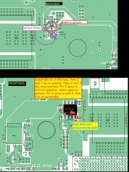
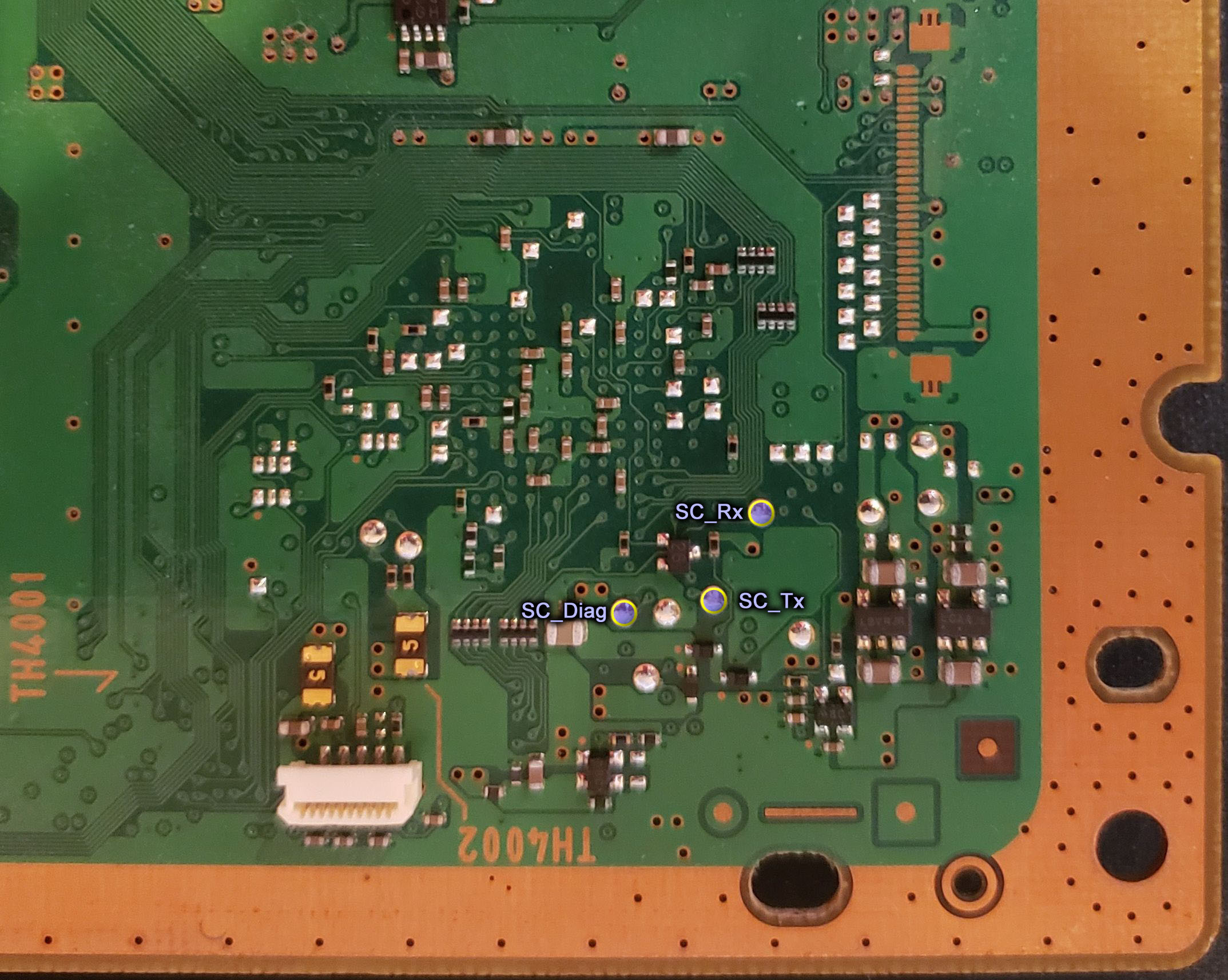
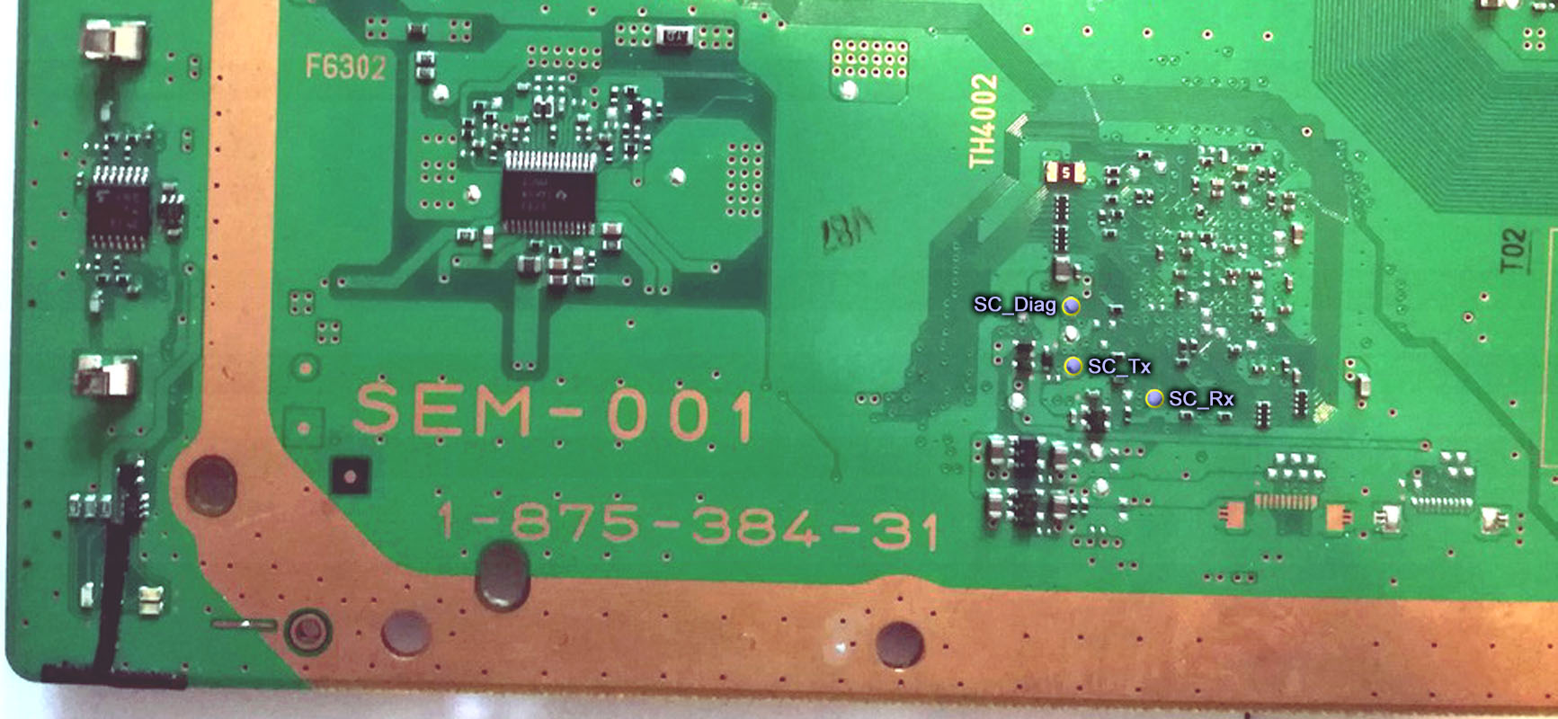
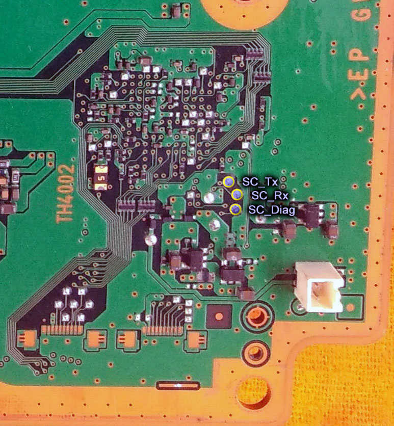
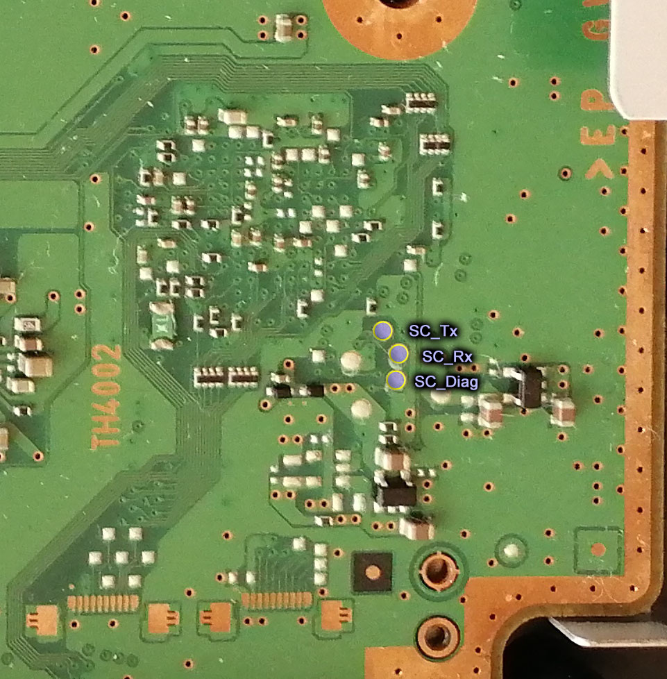
Solder a wire to the RX, TX, and DIAG test pads on your motherboard.
Note, you do not need a DIAG wire for these models.
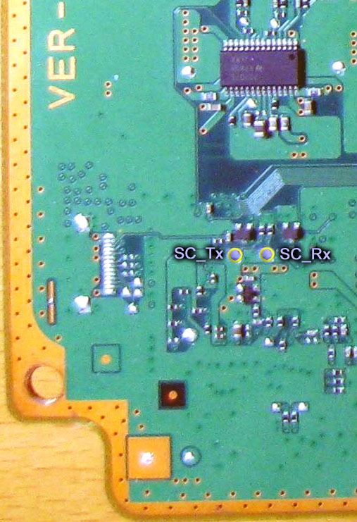
Note, you do not need a DIAG wire for this model.
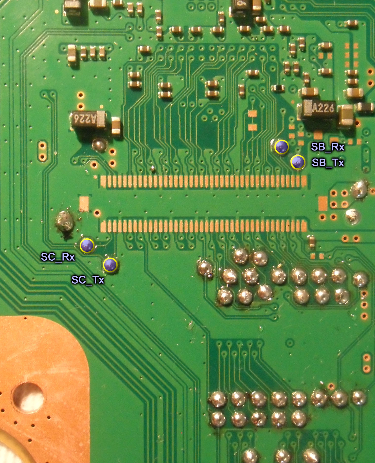
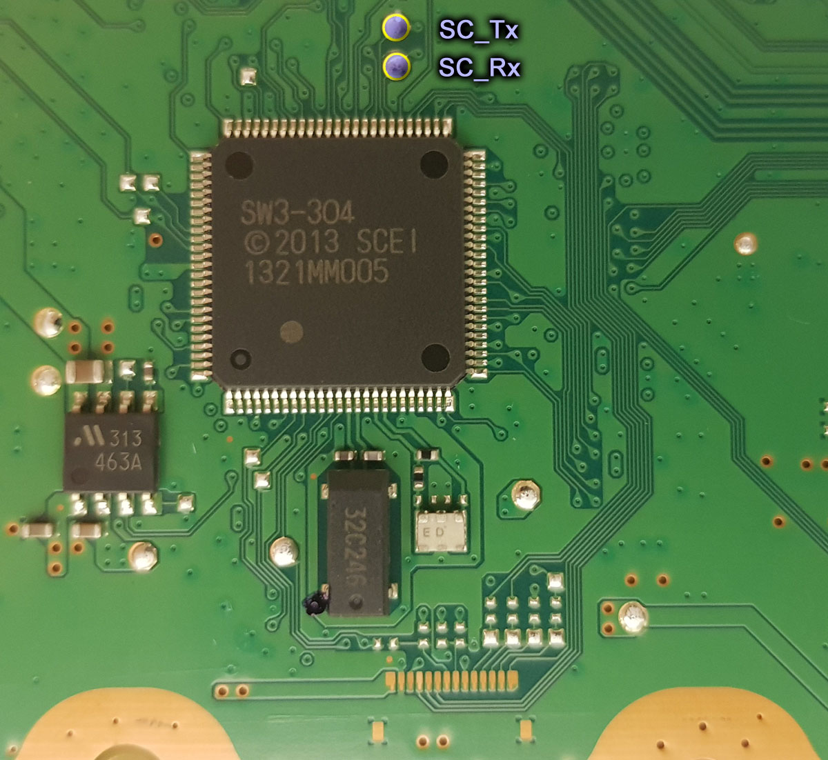
Note, you do not need a DIAG wire for these models. Also, in the picture below SC = SYSCON and SB = South Bridge. You can connect to the south bridge UART using those pins. But that's a more advanced process I won't cover in this tutorial. SC_RX and SC_TX are the pins you need.
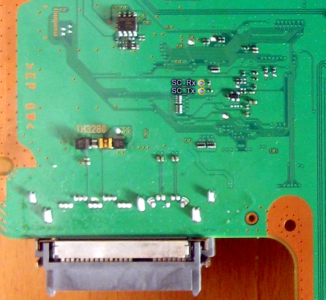
MSX-001, MPX-001, NPX-001, PPX-001, PQX-001, RTX-001, and REX-001. Note, you do not need a DIAG wire for these models.
In the setup CHECK THE BOX "Add PYTHON to PATH." This will allow you to use a windows CMD terminal to access the SYSCON. View attachment 33440
Plug the USB UART adapter into your computer.
Be sure your adapter is set to 3.3v. Some adapters are selectable between 3.3v and 5v. Consult you adapters documentation to be sure it's set to 3.3v! Otherwise it could destroy the SYSCON chip and your console!
Navigate to Device Manager and find which COM PORT windows assigned the USB adapter.
On windows 10 you can just search for "device manager." Then look under Ports for the USB adapter. Mine was given the name "Prolific USB-to-Serial Comm Port (COM4)." The information I need is the "COM4", that's what I'll need to put into the command line to gain acces to my SYSCON. Yours may be different. If you don't recognize the name it was given and are not sure which one it is, just unplug the adapter and watch to see which one disappears, then plug it back in and it should appear. Remember which USB port you plug the adapter into and use the same one from now on. It may assign a different COM port if you use a different USB port.View attachment 33443View attachment 33442
Now open a Command terminal as an Administrator.
On windows 10 you can just search for "cmd", then right click on the app and choose "run as administrator" in the dropdown box.View attachment 33445
You need to install some needed dependencies now. First, type in the following command.
Code:
pip install pyserial
Follow the prompts if there are any. Next, type in this command:
Code:
pip install pycryptodome
Follow the prompts if there are any. When I first did this it prompted me for an update and explained how to do it. So just follow instructions. You should get a message confirming a successful install after each command. These dependencies must be installed or the SYSCON script won't work! Also, you will get errors about PYTHON not being recognized if you didn't check the Box to add PYTHON to path when you installed it.
Now you are ready to gain access to the SYSCON.
Mullion SYSCON's (A - K Models, COK-001 to DIA-002)
External Access Mode: Easier to access, less you can do.
Connect RX & TX wires. DO NOT CONNECT DIAG.
Connect GND on your USB UART adapter to a GND on the PS3
DO NOT ground DIAG! Leave it unconnected for now.
We are just grounding the USB adapter to the console. The RF shield is the most convenient place to ground the USB adapter to. Or the copper ring around the perimeter of the motherboard will work. Alligator clips work great. You do not need to solder a connection! This is just to be sure the computer and PS3 are sharing the same GND reference. It's not strictly necessary, but good practice.
Be sure that the PSU is plugged in. To both the 5v and 12v connectors. Technically, the 2 prong 12v connector is not needed to power and access the SYSCON, but you will get an error without the 12v connector if you attempt to power on. Just be aware of that.
Flip the PWR rocker if your PS3 has one, or plug it in so that the standby LED illuminates.
Open the folder containing the SYSCON python script you downloaded earlier. At the top of the window there is a filepath box. Click on the file path and it'll highlight. If you type CMD into this bar, it will open a terminal with that folder already mounted. This saves you the trouble of manually changing the directory.
Now you are ready to enter the command string needed to run the SYSCON script. You can do that using the following formula. "python ps3_syscon_uart_script.py [COM port of your adapter] [CXR or SW]. Note if your console is an A - K model (COK-001/2/2W, SEM-001, or DIA-001/2) then you must use the CXR command. For example, this is the command I use for my A model PS3:
Now type in AUTH or auth. It is case sensitive, so if one doesn't work try the other. If you get Auth1 response invalid, after trying it both ways, then you got the RX and TX wires reversed. Turn off the console and switch the wires around. It's important you close the terminal and reset the console back to standby. Repeat step 1-5. This time it should say Auth Successful.
Now you can use External commands. The one you're most interested in is ERRLOG, which returns the last 32 codes stored. Luckily you don't have to retrieve them 1 at a time. You can copy the code below and press CTRL+V to paste them into the CMD terminal! It will automatically run all of them at one after the other. ERRLOG GET 00 returns the most recent error code. ERRLOG GET 01, returns the second most recent, and so on. This is Hexadecimal format, so after 09, the tenth error code is 0A!:
Code:
ERRLOG GET 00
ERRLOG GET 01
ERRLOG GET 02
ERRLOG GET 03
ERRLOG GET 04
ERRLOG GET 05
ERRLOG GET 06
ERRLOG GET 07
ERRLOG GET 08
ERRLOG GET 09
ERRLOG GET 0A
ERRLOG GET 0B
ERRLOG GET 0C
ERRLOG GET 0D
ERRLOG GET 0E
ERRLOG GET 0F
ERRLOG GET 10
ERRLOG GET 11
ERRLOG GET 12
ERRLOG GET 13
ERRLOG GET 14
ERRLOG GET 15
ERRLOG GET 16
ERRLOG GET 17
ERRLOG GET 18
ERRLOG GET 19
ERRLOG GET 1A
ERRLOG GET 1B
ERRLOG GET 1C
ERRLOG GET 1D
ERRLOG GET 1E
ERRLOG GET 1F
Hold SHIFT+UP to highlight the text in the CMD terminal. Then press CTRL+C to copy it. Open notepad and paste the code there. Then save it so you have a record of the console's errorlog.
Note: The errorlog only holds 32 errors. So if you do a bunch of testing, each new error will force the oldest error off the end of the log. This errorlog is a record of the console's history and can be useful to piece together a story about what happened. So it's best not to test the console a bunch of times. Instead retrieve the errorlog first thing after experiencing a YLOD, to avoid loosing important clues.
Don't take a picture of your errorlog. It takes about 10 posts or so before you can directly attach it to the forum. So you'll have to upload it to Imagur before you can insert it using the "image" button in the toolbar. It's easier to use the "insert" --> "code" option instead! Just copy your errorlog from the TXT file you created in notepad. Side note: You can also find the spoiler quote in the insert button as well. That's sometimes useful to keep long posts manageable. I used them a bunch in this post, for example.
The error codes are followed by a timestamp. However, timestamps are in a wierd format when retrieved using EXTERNAL access mode (CXR), so you don't know when the errors occured! You can tell if they occured at the same time if the characters match, tho. That can be helpful. Timestamps a big piece to the console's history. If you gain INTERNAL access (CXRF), they will show the date/time each error occurred. So that's one good reason to continue on.
Internal Access Mode - Unlocks more commands and controls
Okay, internal mode is pretty easy. However it's only for A - K models (COK-001/2/2W, SEM-001, DIA-001/DIA-002).
AUTH in external CXR mode as normal.
EEP GET 3961 01 --> should return "00000000 FF"
EEP SET 3961 01 00 (changes the bit to allow internal access mode).
be very careful that you are only changing address 3961. Double check that you didn't accidentally type in the wrong numbers! This will have to be fixed if you do, but you will need to know what it was before we can set it back!
EEP GET 3961 01 (verify the change) --> Should now return "00000000 00".
Shut off console & close the CMD prompt/terminal. Connect the Diag wire to GND and turn console back on. It will beep 3 times and start flashing because the checksum doesn't match anymore. This is normal! We're going to fix that next...
You need to use internal command CXRF now. Here's an example of the commands I have to use every time I gain access for a test, but you'll have to change the "COM4" to whichever comm port your usb to serial device was assigned. You can find it under usb devices in the device manager.:
Code:
CD C:\Users\HTPC\Desktop\PS3\SYSCON
python ps3_syscon_uart_script.py COM4 CXRF
AUTH (Uppercase). It should say "AUTH successful." If so, you're in!
eepcsum --> will return addresses that "should be" somthing like "0x0038". The address you need to change is the line after the "sum:0x0100" line. The sum indicates the mismatch. Ignore the line before of after, the address you want to change is the one immediately following the sum line. So for example if the that line reads "Addr:0x000039fe should be 0x0038" then you do the following...
w 39fe 38 00 (don't just copy this command. yours could be different! Just put it in like this example, based on your actual checksum mismatch. For example, if your address should be "0xff38" then your command should be "w 39fe 38 ff". Hit enter...
--> should just go to the next line or say write successful, I don't remember (you only have to do this once per console. Notice that the 00 and 38 are swapped? That is endian byte swapping. Be sure you enter this in correctly, or you'll have to do another write to fix it. But you can get it wrong and fix it. Just don't shut off the console until it's correct!
r 39fe 02 (validate the change) --> If you did it right the byte swapped number you changed will show 38 00 below the dashed line. Alternatively, you can type in the command eepcsum again. If the checksums match now, then the "sum:0x0100" line will not be there anymore and the console will start normally now. Everything is as it should be. Please note that this process only changes one byte. If you have 2 checksum mismatches, that means you accidentally changed something else during step 3. That's why you need to be very careful that you are only changing address 3961.
Here is an example of me doing the above process on a COK-002...
Code:
Microsoft Windows [Version 10.0.19042.1165]
(c) Microsoft Corporation. All rights reserved.

C:\Users\HTPC\Desktop\PS3\SYSCON>python ps3_syscon_uart_script.py COM4 CXRF
>$ AUTH
Auth successful
>$ eepcsum
eepcsum
Addr:0x000032fe should be 0x528c
Addr:0x000034fe should be 0x7115
sum:0x0100
Addr:0x000039fe should be 0x0038
Addr:0x00003dfe should be 0x00ff
Addr:0x00003ffe should be 0x00ff
>$ w 39fe 38 00
w 39fe 38 00
w complete!
[mullion]$
>$ r 39fe 02
r 39fe 02
+0 +1 +2 +3 +4 +5 +6 +7 +8 +9 +A +B +C +D +E +F
-----------------------------------------------
38 00
>$ eepcsum
eepcsum
Addr:0x000032fe should be 0x528c
Addr:0x000034fe should be 0x7115
Addr:0x000039fe should be 0x0038
Addr:0x00003dfe should be 0x00ff
Addr:0x00003ffe should be 0x00ff
Turn off the console and turn it on again. The standby led will be solid red and stop flashing. That's because the checksum matches and you successfully gained internal access.
From now on you will connect RX, TX, and DIAG. Then use CXRF mode to AUTH in (Uppercase). Example code):
Code:
Microsoft Windows [Version 10.0.19044.1466]
(c) Microsoft Corporation. All rights reserved.

C:\Users\HTPC>CD C:\Users\HTPC\Desktop\PS3\SYSCON

C:\Users\HTPC\Desktop\PS3\SYSCON>python ps3_syscon_uart_script.py COM5 CXRF
>$ AUTH
Auth successful
>$
Just be sure to check the COM port your serial adapter was assigned in windows. The last time I used mine it was COM4, but today it was COM5. Annoying, but if you're having trouble double check that. Also you want to "AUTH" in (uppercase). You can actually "auth" in (lowercase), but it'll only let you retrieve the errlog. If you try to use the other commands it'll say "unknown command." So be sure to "AUTH" in
Here are the internal commands I recommend using...
bringup starts the console and displays a log of the power sequence. That's very useful for diagnosing. It allows you to see "when" an error occurred during the power sequence and can sometimes give you clues about the error, such as the BitTraining error in the following example from an A0403034 (BGA/Bump defect)...
Another useful internal only command is becount. It displays the consoles usage history:
Code:
>$ becount
becount
Bringup : 1651 times
Shutdown: 760 times
Power-on: 80day 21hour 09min 20sec
It would help out the community alot if you post the becount and bringup with your errlog.
Sherwood SYSCON's (All PS3's from L models onward, VER-001...)
Note: Beginning with L models (VER-001) SONY began using a different SYSCON Firmware called "Sherwood" (SW for short). These models do not have internal/external modes. You do not need a DIAG wire and you don't have to mess around with EEPROM to enable internal access mode, since it's enabled by default!
Connect RX & TX wires. Sherwood SYSCON's DO NOT NEED A DIAG WIRE.
Connect GND on your USB UART adapter to a GND on the PS3
We are just grounding the USB adapter to the console. The RF shield is the most convenient place to ground the USB adapter to. Or the copper ring around the perimeter of the motherboard will work. Alligator clips work great. You do not need to solder a connection! This is just to be sure the computer and PS3 are sharing the same GND reference. It's not strictly necessary, but good practice.
Be sure that the PSU is plugged in. To both the 5v and 12v connectors. Technically, the 2 prong 12v connector is not needed to power and access the SYSCON, but you will get an error without the 12v connector if you attempt to power on. Just be aware of that.
Plug in the PS3 so that the standby LED illuminates.
Open the folder containing the SYSCON python script you downloaded earlier. At the top of the window there is a filepath box. Click on the file path and it'll highlight. If you type CMD into this bar, it will open a terminal with that folder already mounted. This saves you the trouble of manually changing the directory.
Now you are ready to enter the command string needed to run the SYSCON script. You can do that using the following formula. "python ps3_syscon_uart_script.py [COM port of your adapter] [SW]. For example...
Now type in AUTH or auth. It has been reported that "AUTH" in uppercase enables external commands and "auth" in lower case enables internal commands. I have not tried this myself, since I mainly work on Mullion SYSCON's. So try it out if the commands you want to use aren't working.
If you get Auth1 response invalid, after trying it both ways, then you got the RX and TX wires reversed. Turn off the console and switch the wires around. It's important you close the terminal and reset the console back to standby. Repeat step 1-5. This time it should say Auth Successful.
If you AUTH in uppercase, you can use External commands. The one you're most interested in is ERRLOG, which returns the error codes. Luckily you don't have to retrieve them 1 at a time. You can copy the code below and press CTRL+V to paste them into the CMD terminal! It will automatically run all of them at one after the other. ERRLOG GET 00 returns the most recent error code. ERRLOG GET 01, returns the second most recent, and so on. This is Hexadecimal format, so after 09, the tenth error code is 0A!:
Code:
ERRLOG GET 00
ERRLOG GET 01
ERRLOG GET 02
ERRLOG GET 03
ERRLOG GET 04
ERRLOG GET 05
ERRLOG GET 06
ERRLOG GET 07
ERRLOG GET 08
ERRLOG GET 09
ERRLOG GET 0A
ERRLOG GET 0B
ERRLOG GET 0C
ERRLOG GET 0D
ERRLOG GET 0E
ERRLOG GET 0F
ERRLOG GET 10
ERRLOG GET 11
ERRLOG GET 12
ERRLOG GET 13
ERRLOG GET 14
ERRLOG GET 15
ERRLOG GET 16
ERRLOG GET 17
ERRLOG GET 18
ERRLOG GET 19
ERRLOG GET 1A
ERRLOG GET 1B
ERRLOG GET 1C
ERRLOG GET 1D
ERRLOG GET 1E
ERRLOG GET 1F
Hold SHIFT+UP to highlight the text in the CMD terminal. Then press CTRL+C to copy it. Open notepad and paste the code there. Then save it so you have a record of the console's errorlog.
Note: The errorlog only holds 32 errors. So if you do a bunch of testing, each new error will force the oldest error off the end of the log. This errorlog is a record of the console's history and can be useful to piece together a story about what happened. So it's best not to test the console a bunch of times. Instead retrieve the errorlog first thing after experiencing a YLOD, to avoid loosing important clues.
Don't take a picture of your errorlog. It takes about 10 posts or so before you can directly attach it to the forum. So you'll have to upload it to Imagur before you can insert it using the "image" button in the toolbar. It's easier to use the "insert" --> "code" option instead! Just copy your errorlog from the TXT file you created in notepad. Side note: You can also find the spoiler quote in the insert button as well. That's sometimes useful to keep long posts manageable. I used them a bunch in this post, for example.
If you auth in lowercase, you can use most of the internal commands. The most useful is errlog. This will retrieve all 32 error codes with their timestamps. This is more useful to figure out the sequence of events! I suggest you always auth in. It's more useful.
SYSCON Commands:
Now you can now use internal commands like "lasterrlog," "bringup," "powerstate," "errlog," and more. You can also adjust fan curves without custom firmware!
becount shows a total count of startups, shutdowns, and PWR on time. That can give you an idea of how the console was used and how much wear and tear it has. Maybe it'll help you decide if the console is worth repairing. For example, a console with less usage time might be worth saving, because it's likely to last a long time. Also error codes 40 3034 are known to be associated with RSX issues only a reflow/reball might fix. That's a time consuming and difficult procedure only experienced technicians should attempt. Many repair shops consider these consoles not worth repairing. So this error code can save them alot of time and expense diagnosing the problem.
bringup will start the console and show a log of the power on sequence. If there is an error it can provide useful information about when/where the error occurred. You should be sure that the power supply is fully connected to avoid errors about the 12v not being connected.
powerstate lists the major power systems and whether they are on or off, or available. Run this after bringup, so that the console is on. Otherwise, of course they would be off.
errlog will list all 32 errors in the log with their timestamps. I suggest you run this after the above 3 commands in the order presented. Then copy the CMD lines into notepad. Post that on the forum using the Insert --> code button in the top toolbar of the reply box. That'll be helpful for us to help you. Also, please give us a complete history of your console. Was it sealed when you got it? What work have you don on it since? Did you notice any damage? Maybe post a picture of the Motherboard front and back. Please don't be ashamed to admit you accidentally damaged something. It happens! We just don't want to spin our wheels guessing at what's wrong when you scratched a trace deliding the CPU, or shorted a wire attempting a NEC/TOKIN replacement. Whatever work has been done on the console is relevant! The error codes are just part of the story.
tmp get 0 and tmp get 1 are useful. Temperature zone 0 is the CPU and 1 is the RSX. So by typing those in while the console is running you can record temperatures in real time without soft moding! Also, duty get 0 will show the current fan percentage!
With internal access mode you can even adjust the fan curves! You can dial them in to be more aggressive and keep the console cooler. Or you can lower the thermal shutdown temperature so the console will overheat at a lower temperature, thus improving reliability. Check out, "Syscon fan settings (Coordinate Graphs)"if you'd like to learn more.
For Example, here's the default COK-001/2 fan curve. The following code could be copied and pasted into the CMD terminal to write these to the fan table. Upon reboot they will become permanant. So you can change these to tighten the curve as you like. And you can use this default code to revert it back.
Hi there, my PS3 Phat with PS2 Support (CechA01) died after a couple of weeks after the NEC replacement and I really want to rescue it so now I bought a USB TTL adapter with 3,3V. The question I now have is: Where do I connect the diag pin from the Mainboard to? Rx and Tx are clear, but where goes diag?
PS: I am planning to harvest a 65 nm GPU from a CechL03 Ps3, but first I need to figure out whats wrong with it.


.JPG")


 . Well... Perhaps it's time to reball one more time with 0.55 balls.. Maybe better to delid RSX so that the weight doesn't squish the balls too hard. Fine, so I lifted the chip and noticed that the green solder mask has started to look damaged...The pads tails were getting more exposed, one pad got ripped. I repaired that, but the PCB mask is there for a reason too. Once the pads areas widens and there are no 'borders' to restrict them, the balls melt and spread over wider area and can easily catch on to neighboring ones that are on free roam ... It's time to paint over the damages with the curing ink. The damage was rather extensive, so the painting took some time...