@RIP-Felix Alright feedback time
Ok so to start with I baked two SEM (I think they were the SEM ones) boards for 7 hours (scrap boards so not overly fussed if they popcorned while configuring the machine). Straight forward, into the oven with a thermocouple sticking in. 110c or there about for the whole time.
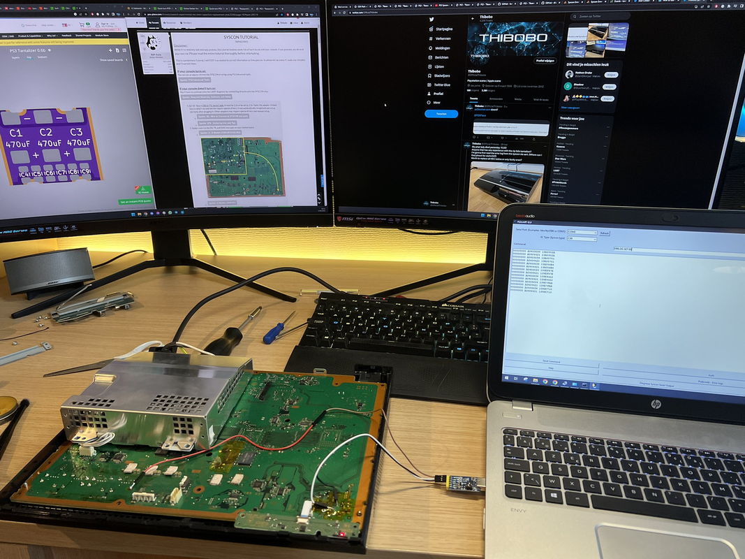
BGA Machine:
So to start with I used
@Shawn Shakir 's profile for the Achi Pro SC as a base.
L1 0 d1 360 r2 1.00
L2 190 d2 30 r3 1.00
L3 200 d3 25 r4 1.00
L4 210 d4 25 r5 1.00
L5 220 d5 25 r6 1.00
L6 230 d6 25 r7 end
hb 230. (I didn't know what this was initially)
Shawn's post suggested that he uses the bottom heater at 280 to get the board heat reporting at 160. I tend to overshoot the reported 160 pretty quickly if I have it at 280 however, we'll revisit this in a moment. Also for clarity, this is 280 reported from the built-in thermocouple that sticks up from the middle of the heating plates (but not touching the board) and the 160 is on the additional thermocouple attached close to the RSX with some aluminium tape. I also had a 3rd Thermocouple that I got from Aliexpress taped to the bottom of the board in the opposite location to ensure some level of consistency in board temp reporting.
So on the overshooting, I've found that L1 D1 360 is probably more time than I need at this stage. Either that or I need to bring the temp of the lower heater down a bit initially.
However, what I've found is that as I progress through the stages of the profile even at L6 my RSX solder wasn't getting molten. So I amended the profile to go up to a reported L7 240 and L8 245. Even then though I wasn't having much luck when the top thermocouple near the RSX was reporting 240etc. At this point I started playing with the bottom heater, I pushed that up to 310c and was getting around 200-210ish reported for the board temp prior to the top heater kicking in. The idea was to have the bottom heater do most of the work and the top heater just push us over the edge.
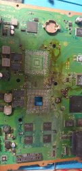
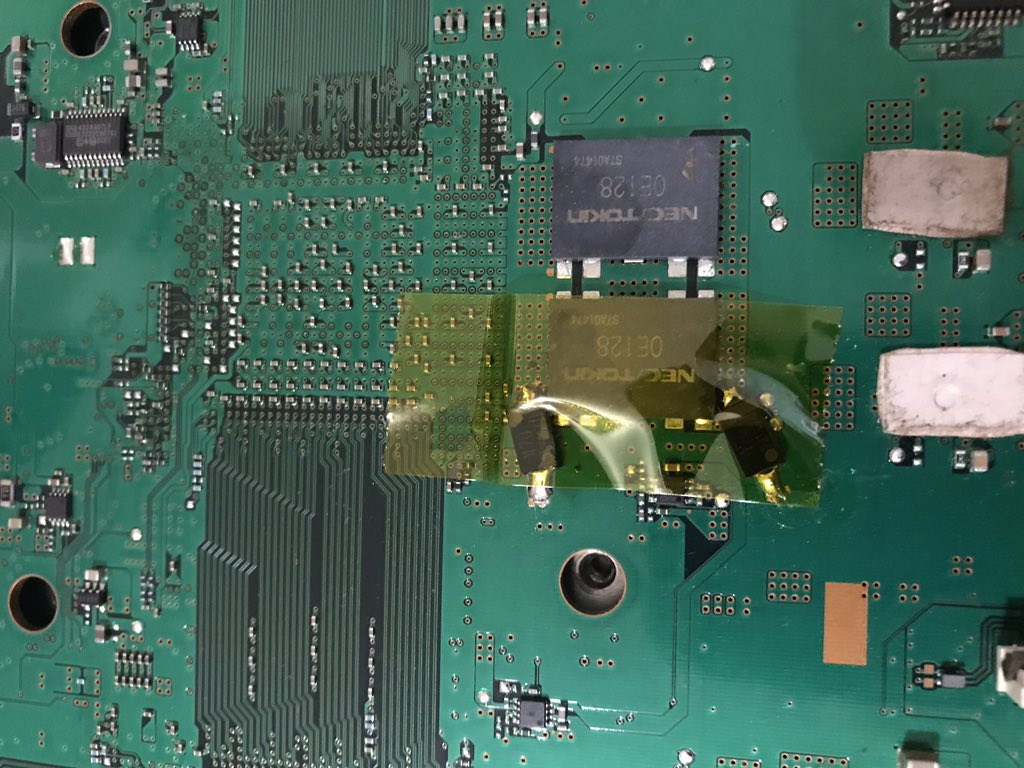
This combination worked to get me to the melting point but, also proved fatal to one of the boards. The reported board temp rose to 240-250, RSX was molten but small caps around it were acting like it was movie night. Now for complete transparency, I didn't put aluminium tape or foil on top of them, so they were in a direct sunbathing position. I may have been able to save them if I'd done this but I was being cheap on not using my tape. Lesson learnt.
At this point I was scratching my head a bit, the reported temps are much higher than I want the board to be getting to but equally nothing seemed to be hitting a melting point lower than that. At this point, I decided to look into what "hb 230" actually meant. Turns out it's the maximum temp for the top heater output.
I've upped that ever so slightly to 235.
This is pretty much where I'm at currently. I lifted the CELL on the same board and nothing went catastrophic with the settings above (and I splashed out on some aluminium tape this time to practice protecting surrounding components) but it felt more like a "fake win" that something that would be consistently repeated.
So I don't know at this point, more playing around with scrap boards tonight trying to dial something stable in.
I've got a COK-002 board baking for 10 hours (not going to put this onto the BGA machine until I'm confident in the profile) and a DAI-002 board. 10 hours is about the max I can leave the oven unattended, two small children could theoretically get into the garage and touch it so I can only do it while being attentive)
If anyone has any advice at this point by all means.
Edit: Image of board gore for engagement.

 So now I'm more motivated than ever.