@Fallen777 im not sure if what im going to said applyes to all motherboard models, but i now at least some of them does this
Imagine the line is like a
T... in the horizontal lline at top of the "T" we have A at left (syscon) and C at right (the service connector). And the diag pad is B at bottom of the "T", ok ?... well...
If the circuit is like that and we burn the diag pad (B at the bottom of the T) then it doesnt matters much because the connection in between A and C is still there
The other design is if we have A---B---C in a single line. In this case if we damage B then we are cutting the connection in between A and C. In this case the only solution would be to find a alternative solder point near A
But im not sure if this is your case, this is something you need to check in your specific motherboard model, and every line could be traced differently
-------
The other thing we was trying to explain is... the circuit is designed to solder some resistors in some of the lines that goes from syscon to the service connector... but this resistors doesnt exists in the retail motherboards
Take a look at the comments of the service connector for PS3 slim motherboards (named C??? in this page), im just using this one as an example because i was looking at it some weeks ago and there are good photos about them, but in other motherboard models happens the same and could be a bit different
https://www.psdevwiki.com/ps3/Service_Connectors#CN.3F.3F.3F.3F
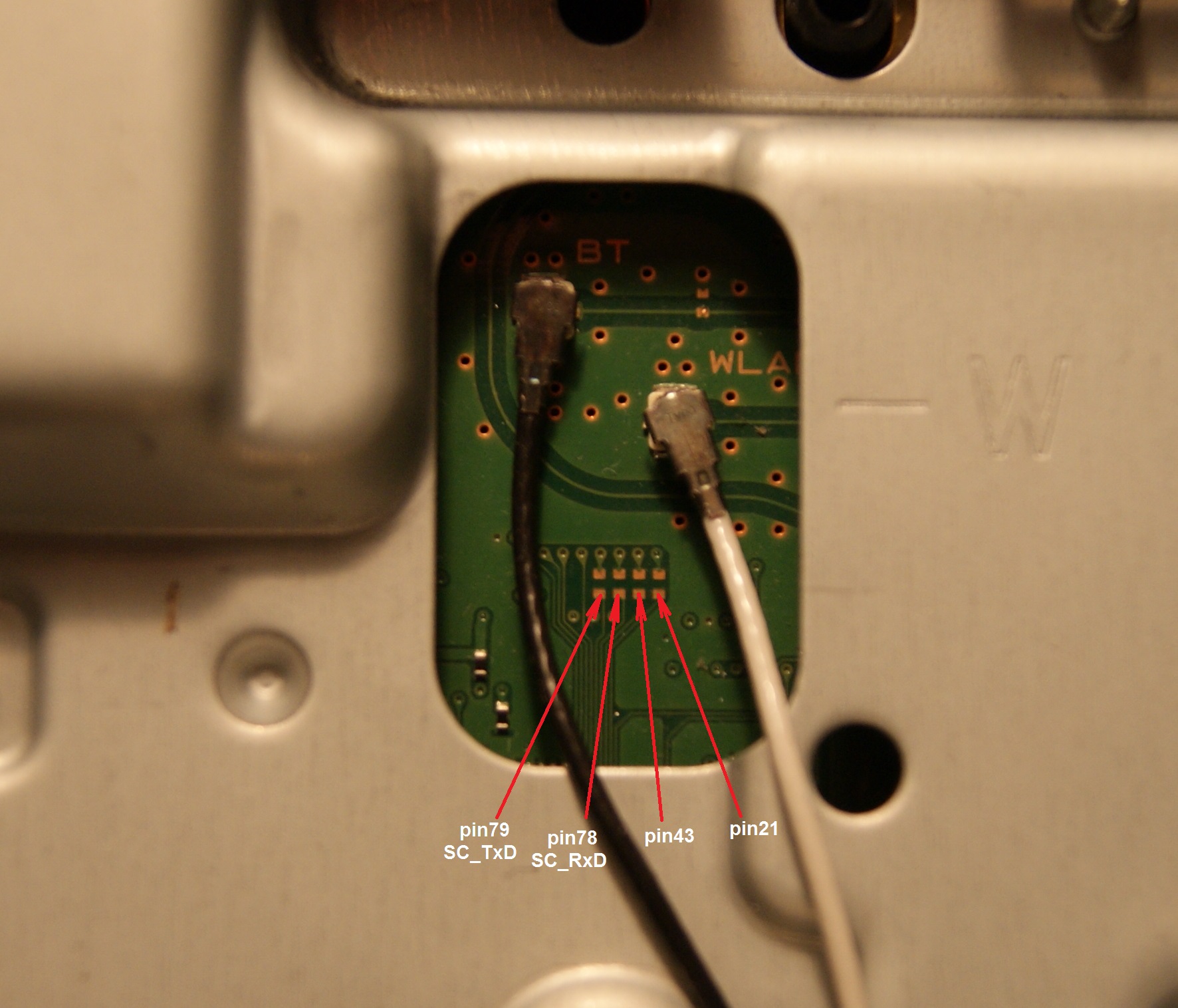
Inside the table is mentioned several times that the lines goes "throught missing SMD components"... like in this photo
This pads are intended to solder a resistor with 0 ohms (a bridge)... without them the pins of the service connector are not connected to anything
So... to restore the service connector is needed to restore those resistors too
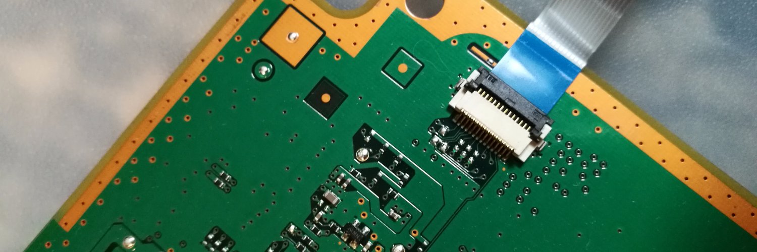
In this other image can be seen too, here the service connector is present... but is not going to work, see those 6 solder pads located in front of the connector at its middle ?
Are 3 missing resistors... so... in this photo there are 3 pins of the connector that are "disconnected"