I don't know. He should run the commands first. Here is an example of a working HDMI chip. If you see that video setting state is unset under [AV Setting], it is RSX related GLOD, or a special glod like you are calling it.
Oh lol. I did not check all the messages properly. Yes, you can see it's stuck waiting for the resolution, but RSX is not setting it.. So... Replace/reball/reflow. Not a simple fix.
I used SysconReader and I only have these logs.
Before the reflow, I tried to read the errors about 15 times, because the program crashed randomly and as long as I waited it did not continue.
After the reflow, read them the first time.
Now I will try to install python and see what else I can do.
I don't know. He should run the commands first. Here is an example of a working HDMI chip. If you see that video setting state is unset under [AV Setting], it is RSX related GLOD, or a special glod like you are calling it.
Hi, you said those hdmi chstat 0 output is from a working HDMI chip, but it was still having WaitResolution(just like mine GLOD)? Can you elaborate it a bit? Is SSM State WaitResolution the one I should expect when everything working?
Hi, you said those hdmi chstat 0 output is from a working HDMI chip, but it was still having WaitResolution(just like mine GLOD)? Can you elaborate it a bit? Is SSM State WaitResolution the one I should expect when everything working?
I'm sorry I didn't notice that you already ran the chstat command. I have already replied yesterday that your RSX is dead, you can't fix it easily. But my example was the same as yours, when the RSX was also dead (not setting the resolution). It was to show that the HDMI chip itself was ok, because Victor was suggesting replacing it. I just tried to show that there is no point, because the fault is inside RSX. Both your and my example show a problematic RSX, but a working HDMI chip.
Oh lol. I did not check all the messages properly. Yes, you can see it's stuck waiting for the resolution, but RSX is not setting it.. So... Replace/reball/reflow. Not a simple fix.
I'm sorry I didn't notice that you already ran the chstat command. I have already replied yesterday that your RSX is dead, you can't fix it easily. But my example was the same as yours, when the RSX was also dead (not setting the resolution). It was to show that the HDMI chip itself was ok, because Victor was suggesting replacing it. I just tried to show that there is no point, because the fault is inside RSX. Both your and my example show a problematic RSX, but a working HDMI chip.
Hi, I have no problem with a dead RSX or Cell, but I'm still not fully convinced it's dead. It at least had booted successfully with hdmi config screen and into XMB when I did a bunch of settings and tweaks with no artefacts whatsoever, before I packed it up and try again. Before that it was power related issue I had replaced caps and fuses. Can you explain what should I expect from the chstat command? Does WaitResolution mean I should already see a screen(like a "hdmi detected, should we switch to hdmi" message)?
EDIT: I just saw your update, too. Fair enough. I'll try dig a bit more myself
Power Control Topology - Part 2 (Power Good & Voltage Regulation)
The PlayStation 3 Power Supply Unit (PSU) outputs 2 voltages from which all other system voltages are derived - 12V_MAIN and 5V_EVER. I made the following flowchart of a COK-001 to illustrate. View attachment 35543
12V_MAIN is the one from which most other system voltages are derived (5V, 3.3v, 1.8v, 1.7, 1.2, 1.0 etc). The CPU/GPU/SB, are all powered from this 12V_MAIN. But each one of them has a chain chips before the correct voltage can get to them. The purpose of these chips is to provide stable voltage and control of when that voltage is delivered.
For example, the CPU's 1.0V_BE_VDDC is produced by its Voltage Regulation Module (VRM). It includes IC6103, a buck controller which drives IC6104, IC6105, IC6106 buck converters. That controller is enabled by the syscon chip at the appropriate time to turn on the CPU. IC6107 is involved in the coordination of this effort. So too are the NEC/TOKIN bulk filtering capacitors. And also the array of MLCC bypass caps. Collectively they constitute the CPU's Voltage Regulation Module.
The RSX has it's own VRM, the SB too. Most subsystems have have an IC controller that enables their voltage at the appropriate time in the Power On Sequence. The Voltage flowchart I made above is the general manner in which these subsystems recieve their voltages. Not every IC in the PS3 is listed, just the major ones involved in producing the system voltages marked by a square box. Also that image was based off the COK-001 Service Manual. It does not apply to to all models, but can be used as a general guide for them. Obviously, the PS2 Hardware section will not be included in non-backward compatible models.
How does this relate to power good? Well, if each system voltage in a box in that image has a controller IC that is monitoring it's output voltage. If that voltage is within regulation, it will report power good to the SYSCON "system control." If any one of them falls out of regulation and reports no power good, the syscon will refuse to boot.
The voltage flowchart above image combined with the one below should make diagnosing and troubleshooting easier. View attachment 35538
I made this one from scratch, with high enough resolution to read the Labels and to still upload to the forum. I was really pushing the limit here. This will make it easier for you to search the service manual when you find a voltage that's missing. When I say this took a long time to make, it's an understatement.
Speaking of time consuming projects. Here's more fruit from that effort.
ATA = Hard Drive Interface
BC = PS2 Bridge Chip
BEI = Redwood Broadband Engine Interface Controller (AKA RC)
CE = Control Enable
CELL BE = CPU ("Cell Broadband Engine")
CG = Clock Generator
CLK = Clock
CONT = Control
CTL = Control
EE = Emotion Engine (PS2 CPU)
EIB = Element Interconnect Bus
EN = Enable
ESW = Ethernet Switch or Switchable
FB = Feedback
FlexIO = Redwood Rambus FlexIO CPU/GPU Interface
GS = Graphics Synthesizer (PS2 GPU)
MC2 = ? (VDDIO à BE_SPI, CHKSTP, JTAG, TBEN, & P_L_BYPASS)
MIC = Yellowstone Memory Interface Controller (AKA YC)
PCI = PS2 Hardware Interface
PLL = Phase-Locked Loop
PPE = Power Processor Element (main dual threaded CPU)
PWRGD = Power Good
RC = Redwood Broadband Engine Interface Controller (AKA BEI)
RRAC = Redwood Rambus FlexIO CPU/GPU Interface Voltage (VDDR)
RST = Reset
RSX = GPU ("Reality Synthesizer")
SB = South Bridge
SPE = Synergistic Processing Element (8x, 1 disabled for redundancy)
STBY = Standby
SW = Switch
VDD = Positive Field Emitting Transistor (FET) Voltage
VDDA = Positive FET Voltage Supply for Analog Subsystems
X = Rambus XDRAM Memory Subsystem
XDR = Yellowstone XDRAMTM System Memory (Y0_XDR0, Y0_XDR1, Y1_XDR0, & Y1_XDR1)
XGC = XDRAM Clock Generator
XIO = Yellowstone Rambus CPU/XDR Memory Interface ("Extreme Data Rate IO")
YC = Yellowstone Memory Interface Controller (AKA MIC)
YRAC = Yellowstone Rambus CPU/XDR Memory Interface Voltage
Analog Voltage for the core PLL of IC5004, which is an ICS9214 Clock Generator used to support the Rambus XDR memory subsystem and Redwood logic interface.
Do not take the above as gospel. If you notice anything needing updated let me know and I'll edit back as necessary.
Getting back to Power good:
Notice the GPU Buck Controllers (IC6201). It's locate at B5. This controller is what controls power to the RSX. I have labeled the jumper loactions for Enable, which is the signal SYSCON sends to power on the RSX. I also labeled Power Good (PWRGD), which is the signal the controller sends back to the SYSCON about the power regulation. If it's bad, /RSX_POW_FAIL goes low and the syscon throws an error. Which error? 3004 or 1002. Which one is a mystery stil. I hypothesize it depends upon the Step number of the Power On Sequence. Basically, when power good went low. The hypothesis is that earlier step numbers = 3004. Later step numbers = 1002. However, the earliest reported 1002 was 06, and 3004 was 09. So that is inconsistant with my hypothesis. The 06 1002 report could be inaccurate, but reports are all I have to go off of.
The last pad I labeled on the RSX VRM Controller is the voltage feedback/drop jumper. This is what the controller is monitoring to decide if power is good or not. We should be able to probe this point to see voltage drop across RSX_VDDC. If it drops too much it triggers under voltage lock out and the controller will send no power good (PWRGD low). The syscon will error. The CPU has the same and other controllers around the board have a similar function.
Since, preventing voltage drops on the CPU/GPU is important for system stability, the NEC/TOKIN's are a concern. If they can't sustain the voltage for long enough underload, the voltage drop will fall out of regulation. One way to prevent this is to replace failing/aged tokins with new tantalum capacitors. Everyone is already familar with that. But there is another way. By adjusting the power good voltage dropout threshold, so that there is a wider range the voltage can fall before triggering an error.
Adjusting Power Good Threshold
Vid pins VID0-5 on the buck controller form a 6-digit code corresponding to the Vout No load setpoint. Power Good Vmin and Vmax thresholds are relative to that set point. With the stock COK-00X voltage divider values (15K and 20k), Vmin = -163mV. Vmax is always +100mV. The Vout voltage cannot deviate more than that. If it does power good goes low and the SYSCON will error.
In some official SONY refurbished consoles, new resistor values (27K and 10K) change Vmin = -400mV. So the Low Voltage threshold is now more than twice as low, allowing much more voltage ripple before it triggers an error. My hypothesis is SONY did this to reduce the frequency of 1001 and 1002's errors. That would explain why they did it to both buck controllers (CPU and GPU). A sort of admission of guilt that they either set it too aggressively or were compensating for bad NEC/TOKINs without replacing them.
Power good low voltage threshold is there to prevent system instability, but if SONY decided it was okay to loosen it, then perhaps we can follow suit. It could be particularly important because we're seeing a lot of unexplained 1001's recently. Currently, 1002's are assumed to be bad NEC/TOKIN's. Replacing aged bulk filter capacitors certainly works, but just because changing them fixes the error doesn't mean that's the only way to skin a cat.
I have intentionally held off recommending this mod to people, because I'm only freshly aware of it's potential. Before I conclude this is okay to do, I would like to know what the VID at idle is, so we can compare actual voltage measurements with the low voltage threshold. On a console with 1001/1002 errors, Vout should drop more than that before it experiences a YLOD. That means I need oscilloscope measurements of Vout on both the CPU/GPU and PWRGD. Then, by replicating Sony's mod, I would like to see if the error goes away AND the system is stable (requires stress testing)! If so, then we have discovered an easier method of resolving these errors.
Replacing those resistors is fine micro-soldering work that pretty much requires a microscope. And I need oscilloscope measurements of the voltage drop and PWRGD (Cell BE for 1001 and RSX for 1002). So it's not too easy or cheap.
Power-on: 248day - I think the console is giving its own: D
I also have another console that does not through HDMI, but only through AV.
I'm thinking of trying to see if the hdmi chip is the problem or something else?
Power-on: 248day - I think the console is giving its own: D
I also have another console that does not through HDMI, but only through AV.
I'm thinking of trying to see if the hdmi chip is the problem or something else?
What's the board you have? Sounds very much like RSX power related issue. If you did the reflow before getting those 2102 errors, probably is the reflow broke the power line. Try checking the fuses and voltage regulators feeding the RSX.
No, only once and very "slightly"
I heated the board to about 100-120 degrees.
I was afraid of hurting anything.
Is 1.6 ohm normal for RSX NEC capacitors and 2.5 ohm for CELL NEC capacitors?
Still, I think the problem with YLOD started after the cleaning. I cleaned very lightly and thoroughly, like any electronics. With brush and vacuum cleaner.
Before that, it always GLOD, no matter how many times I restarted. Even the fan accelerated when turned on for a long time. I think even holding down the power button went into service mode.
After cleaning and assembling at the first turn on, as far as I remember again GLOD. I put the hard drive in and restarted and since then only a YLOD. Maybe I didn't put the hard drive in nicely and something went wrong as a result?
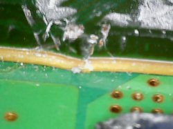
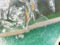
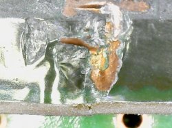
EDIT: Another thing I noticed is that the thermal paste on the RSX has not spread (stay on point), the chip does not heat up, while in the video it is everywhere.
EDIT2: After a pressure test on RSX - GLOD. Obviously need a good reflow or reball.
EDIT3: Finally, just for the record, these are the errors after pressure test..
Code:
>$ ERRLOG GET 00
00000000 A0503035 0B4886EB
>$ ERRLOG GET 01
00000000 A0403034 0B4886E0
>$ ERRLOG GET 02
00000000 A0404002 0B4886DF
>$ ERRLOG GET 03
00000000 A0801002 0B4886B8
>$ ERRLOG GET 04
00000000 A0403034 0B4886AF
>$ ERRLOG GET 05
00000000 A0404002 0B4886AE
>$ ERRLOG GET 06
00000000 A0232102 0B48868E
>$ ERRLOG GET 07
00000000 A0232102 0B488687
>$ ERRLOG GET 08
00000000 A0801601 0B488682
>$ ERRLOG GET 09
00000000 A08014FF 0B488682
>$ ERRLOG GET 0A
00000000 A0801701 0B488682
>$ ERRLOG GET 0B
00000000 A0403034 FFFFFFFF
>$ ERRLOG GET 0C
00000000 A0404002 FFFFFFFF
>$ ERRLOG GET 0D
00000000 A0801601 FFFFFFFF
>$ ERRLOG GET 0E
00000000 A08014FF FFFFFFFF
>$ ERRLOG GET 0F
00000000 A0801701 FFFFFFFF
>$ ERRLOG GET 10
00000000 A0232102 FFFFFFFF
>$ ERRLOG GET 11
00000000 A0232102 FFFFFFFF
>$ ERRLOG GET 12
00000000 A0232102 FFFFFFFF
>$ ERRLOG GET 13
00000000 A0232102 FFFFFFFF
>$ ERRLOG GET 14
00000000 A0232102 FFFFFFFF
>$ ERRLOG GET 15
00000000 A0232102 FFFFFFFF
>$ ERRLOG GET 16
00000000 A0232102 FFFFFFFF
>$ ERRLOG GET 17
00000000 A0232102 FFFFFFFF
>$ ERRLOG GET 18
00000000 A0232102 FFFFFFFF
>$ ERRLOG GET 19
00000000 A0232102 FFFFFFFF
>$ ERRLOG GET 1A
00000000 A0232102 FFFFFFFF
>$ ERRLOG GET 1B
00000000 A0232102 FFFFFFFF
>$ ERRLOG GET 1C
00000000 A0232102 FFFFFFFF
>$ ERRLOG GET 1D
00000000 A0232102 FFFFFFFF
>$ ERRLOG GET 1E
00000000 A0232102 FFFFFFFF
>$ ERRLOG GET 1F
The another console that does not through HDMI is VER-001 and as far as I understood he could not enter Internal Access Mode
Firmware Version: 4.86 (build 50715)
Platform ID: Cok14
Product Code: 00 8E
Product Sub Code: 00 01
Hardware Config: 00000000FFFFFFFF
Syscon Fimware Version: 0B8E.0001000000000006 (EEPROM: 0001000000000006)

Bringup Count: 1028, Shutdown Count: 937
Runtime: 42 Days, 9 Hours, 17 Minutes, 31 Seconds

Error Log
01: A0901001  Sat Dec 18 18:33:41 2021
02: A0801002  Sat Dec 18 09:11:13 2021
03: A0801002  Sat Dec 18 08:55:26 2021
04: A0801002  Sat Dec 18 08:42:32 2021
05: A0801002  Sat Dec 18 08:41:45 2021
06: A0801002  Sat Dec 18 08:41:26 2021
07: A0801002  Sat Dec 18 08:41:05 2021
08: A0801002  Sat Dec 18 08:40:41 2021
09: A0801002  Sat Dec 18 08:40:25 2021
10: A0901001  Thu Dec  2 15:59:09 2021
11: A0801002  Thu Dec  2 15:58:23 2021
12: A0801002  Thu Dec  2 15:58:07 2021
13: A0801002  Thu Dec  2 15:57:58 2021
14: A0801002  Thu Dec  2 15:57:47 2021
15: A0801002  Thu Dec  2 15:57:38 2021
16: A0801002  Thu Dec  2 12:12:48 2021
17: A0801002  Thu Dec  2 12:08:54 2021
18: A0801002  Thu Dec  2 12:08:42 2021
19: A0801002  Wed Dec  1 17:40:07 2021
20: A0801002  Wed Dec  1 17:35:49 2021
21: A0801002  Wed Dec  1 17:27:00 2021
22: A0801002  Wed Dec  1 16:58:33 2021
23: A0801002  Wed Dec  1 16:53:08 2021
24: A0801002  Wed Dec  1 16:43:41 2021
25: A0801002  Wed Dec  1 16:40:58 2021
26: A0801002  Wed Dec  1 16:34:40 2021
27: A0801002  Wed Dec  1 16:06:18 2021
28: A0801002  Wed Dec  1 15:44:52 2021
29: A0801002  Wed Dec  1 15:44:35 2021
30: A0801002  Wed Dec  1 15:44:25 2021
31: A0801002  Tue Nov 30 18:41:58 2021
32: FFFFFFFF  Tue Nov 30 18:34:05 2021
It is a young guy, 42 days in total, isn't it
Rn the machine starts 7/10 times and shuts down if I play any heavy duty games. Interestingly, if I switch the video output to AV or HDMI in 480P, it boots almost guaranteed. I didn't try to play games under this low-res config but I guess it would crash as well.
If I understand correctly, A081002 is the symptom of bad NEC caps.
I am going to order parts and gears to replace those bad caps soon. Once done, I'll report here.
5th system another COK-002 system with these errors:
===================================
ERR 00: 00000000 A0213013 FFFFFFFF
ERR 01: 00000000 A0202120 FFFFFFFF
ERR 02: 00000000 A0202120 FFFFFFFF
ERR 03: 00000000 A0202120 FFFFFFFF
ERR 04: 00000000 A0202120 FFFFFFFF
ERR 05: 00000000 A0202120 FFFFFFFF
ERR 06: 00000000 A0202120 FFFFFFFF
ERR 07: 00000000 A0202120 FFFFFFFF
ERR 08: 00000000 A0202120 FFFFFFFF
ERR 09: 00000000 A0202120 FFFFFFFF
ERR 10: 00000000 A0202120 FFFFFFFF
ERR 11: 00000000 A0202120 FFFFFFFF
ERR 12: 00000000 A0202120 FFFFFFFF
ERR 13: 00000000 A0202120 FFFFFFFF
ERR 14: 00000000 A0202120 FFFFFFFF
ERR 15: 00000000 A0202120 FFFFFFFF
ERR 16: 00000000 A0213013 FFFFFFFF
ERR 17: 00000000 A0202120 FFFFFFFF
ERR 18: 00000000 A0202120 FFFFFFFF
ERR 19: 00000000 A0202120 FFFFFFFF
===================================
It is CPU related as the previous tech delided the CPU and RSX and dented in the PCB that the CPU die is installed on prying off the heat spreader. Also the RSX has a blueish tint to it as well so that is most likely toast as well. They also managed to partially melt the edge of one of the NEC caps by the CPU as well. I am now thinking that deliding chips should come with a big warning or something. In to the parts pile this one goes as well.
Hi, I have no problem with a dead RSX or Cell, but I'm still not fully convinced it's dead. It at least had booted successfully with hdmi config screen and into XMB when I did a bunch of settings and tweaks with no artefacts whatsoever, before I packed it up and try again. Before that it was power related issue I had replaced caps and fuses. Can you explain what should I expect from the chstat command? Does WaitResolution mean I should already see a screen(like a "hdmi detected, should we switch to hdmi" message)?
EDIT: I just saw your update, too. Fair enough. I'll try dig a bit more myself
I think the command is there to see what is going on with the system. I believe "WaitResolution" means the system is literally waiting for the RSX to set the resolution, any resolution, which it is not able to do for some reason. There will be black screen until some kind of resolution is set. But this is for HDMI. I guess you could try AV composite cable to see if there's anything on screen and then switch it to HDMI from there.
Still, even if it's not 100% dead, it's on the way there, I would imagine. Of course, you should inspect the board to be sure there are no knocked off components just like Vyctor was trying to tell you. But yeah, don't hold your breath.
No, only once and very "slightly"
I heated the board to about 100-120 degrees.
I was afraid of hurting anything.
Is 1.6 ohm normal for RSX NEC capacitors and 2.5 ohm for CELL NEC capacitors?
Still, I think the problem with YLOD started after the cleaning. I cleaned very lightly and thoroughly, like any electronics. With brush and vacuum cleaner.
Before that, it always GLOD, no matter how many times I restarted. Even the fan accelerated when turned on for a long time. I think even holding down the power button went into service mode.
After cleaning and assembling at the first turn on, as far as I remember again GLOD. I put the hard drive in and restarted and since then only a YLOD. Maybe I didn't put the hard drive in nicely and something went wrong as a result?
EDIT: Another thing I noticed is that the thermal paste on the RSX has not spread (stay on point), the chip does not heat up, while in the video it is everywhere.
EDIT2: After a pressure test on RSX - GLOD. Obviously need a good reflow or reball.
EDIT3: Finally, just for the record, these are the errors after pressure test..
Code:
>$ ERRLOG GET 00
00000000 A0503035 0B4886EB
>$ ERRLOG GET 01
00000000 A0403034 0B4886E0
>$ ERRLOG GET 02
00000000 A0404002 0B4886DF
>$ ERRLOG GET 03
00000000 A0801002 0B4886B8
>$ ERRLOG GET 04
00000000 A0403034 0B4886AF
>$ ERRLOG GET 05
00000000 A0404002 0B4886AE
>$ ERRLOG GET 06
00000000 A0232102 0B48868E
>$ ERRLOG GET 07
00000000 A0232102 0B488687
>$ ERRLOG GET 08
00000000 A0801601 0B488682
>$ ERRLOG GET 09
00000000 A08014FF 0B488682
>$ ERRLOG GET 0A
00000000 A0801701 0B488682
>$ ERRLOG GET 0B
00000000 A0403034 FFFFFFFF
>$ ERRLOG GET 0C
00000000 A0404002 FFFFFFFF
>$ ERRLOG GET 0D
00000000 A0801601 FFFFFFFF
>$ ERRLOG GET 0E
00000000 A08014FF FFFFFFFF
>$ ERRLOG GET 0F
00000000 A0801701 FFFFFFFF
>$ ERRLOG GET 10
00000000 A0232102 FFFFFFFF
>$ ERRLOG GET 11
00000000 A0232102 FFFFFFFF
>$ ERRLOG GET 12
00000000 A0232102 FFFFFFFF
>$ ERRLOG GET 13
00000000 A0232102 FFFFFFFF
>$ ERRLOG GET 14
00000000 A0232102 FFFFFFFF
>$ ERRLOG GET 15
00000000 A0232102 FFFFFFFF
>$ ERRLOG GET 16
00000000 A0232102 FFFFFFFF
>$ ERRLOG GET 17
00000000 A0232102 FFFFFFFF
>$ ERRLOG GET 18
00000000 A0232102 FFFFFFFF
>$ ERRLOG GET 19
00000000 A0232102 FFFFFFFF
>$ ERRLOG GET 1A
00000000 A0232102 FFFFFFFF
>$ ERRLOG GET 1B
00000000 A0232102 FFFFFFFF
>$ ERRLOG GET 1C
00000000 A0232102 FFFFFFFF
>$ ERRLOG GET 1D
00000000 A0232102 FFFFFFFF
>$ ERRLOG GET 1E
00000000 A0232102 FFFFFFFF
>$ ERRLOG GET 1F
The another console that does not through HDMI is VER-001 and as far as I understood he could not enter Internal Access Mode
Can you clearify? When you say you 'heated the board to 100-120C,' do you mean you used a preheater at those temps before the reflow. Or do you mean you attempted to reflow with those temps?
Edit:
Wow, I've never seen a 50 3035 before! Happened during a pressure test? Can you explain in detail the chain of events? When did the error happen? When you released pressure?
I see the 503035 preceeded by 3034/4002. There is a random 80 1002 in there suggesting the console was on at some point. I'm guessing when you got it to boot with the GLOD it failed after some amount of time with that 1002. Upon the next boot it was 3034/4002. Then you tried another pressure test and it gave the 503035. But without the timestamps or a more detailed explanation of your specific tests, I'm just guessing.
Not that it matters. You clearly have a BGA defect and or bump failure. These errors and response to the pressure test prove it. You need a reball!
Edit 2:
I wouldn't use a vacuum cleaner near a bare PCB (Grounded is fine). They tend to generate a lot of static electricity in the air pulled over a surface. It depends on humidity though.
Stick to compressed electronics duster to get most of the loose stuff off. Then use IPA and a soft brush to get the rest. Blow off the rest of the IPA hiding under the chips and dry thoroughly before use. If removing flux, be sure to soak up the flux contaminated IPA and rinse with fresh IPA. Otherwise when the IPA evaporates, the flux residue will remain. It looks like white dust coating everything. It means you didn't clean thoroughly. It takes a good 2-3 times with IPA and paper towels to rinse it all off after a reflow, I find. It's a PITA!
6th system this time a DIA-002 with these error codes:
===================================
ERR 00: 00000000 A0403034 0BDA9264
ERR 01: 00000000 A0404411 0BDA9264
ERR 02: 00000000 A0403034 0BDA9098
ERR 03: 00000000 A0404411 0BDA9098
ERR 04: 00000000 A0403034 0B922932
ERR 05: 00000000 A0404411 0B922932
ERR 06: 00000000 A0403034 0B92292B
ERR 07: 00000000 A0404411 0B92292B
ERR 08: 00000000 A0902120 0B915098
ERR 09: 00000000 A0403034 0B915098
ERR 10: 00000000 A0404411 0B91508B
ERR 11: 00000000 A0902120 0B915087
ERR 12: 00000000 A0403034 0B915087
ERR 13: 00000000 A0404411 0B915087
ERR 14: 00000000 A0403034 0B914DD3
ERR 15: 00000000 A0404411 0B914DD3
ERR 16: 00000000 A0902120 0B914DCF
ERR 17: 00000000 A0403034 0B914DCF
ERR 18: 00000000 A0404411 0B914DCF
ERR 19: 00000000 A0403034 0B914DC3
===================================
I am going to suspect a RSX issue but if I am lucky it could be something else as there is a lot of rust on the metal shields and it looks like it may have been either under water or at least in a very humid place for this to happen. On further inspection once again the RSX has been delided and the die is a blueish color. There is some very small nicks on the very edge of the RSX PCB that don't look to be impacting any traces but who knows. I guess I could try reflowing the RSX die but I don't have high hopes for this system either now.
This one is definitely RSX. 3034 is a dead giveaway. Not sure if the blueish color matters. Is there a correlation with the color of the die and the condition of the chip ?
Firmware Version: 4.86 (build 50715)
Platform ID: Cok14
Product Code: 00 8E
Product Sub Code: 00 01
Hardware Config: 00000000FFFFFFFF
Syscon Fimware Version: 0B8E.0001000000000006 (EEPROM: 0001000000000006)

Bringup Count: 1028, Shutdown Count: 937
Runtime: 42 Days, 9 Hours, 17 Minutes, 31 Seconds

Error Log
01: A0901001  Sat Dec 18 18:33:41 2021
02: A0801002  Sat Dec 18 09:11:13 2021
03: A0801002  Sat Dec 18 08:55:26 2021
04: A0801002  Sat Dec 18 08:42:32 2021
05: A0801002  Sat Dec 18 08:41:45 2021
06: A0801002  Sat Dec 18 08:41:26 2021
07: A0801002  Sat Dec 18 08:41:05 2021
08: A0801002  Sat Dec 18 08:40:41 2021
09: A0801002  Sat Dec 18 08:40:25 2021
10: A0901001  Thu Dec  2 15:59:09 2021
11: A0801002  Thu Dec  2 15:58:23 2021
12: A0801002  Thu Dec  2 15:58:07 2021
13: A0801002  Thu Dec  2 15:57:58 2021
14: A0801002  Thu Dec  2 15:57:47 2021
15: A0801002  Thu Dec  2 15:57:38 2021
16: A0801002  Thu Dec  2 12:12:48 2021
17: A0801002  Thu Dec  2 12:08:54 2021
18: A0801002  Thu Dec  2 12:08:42 2021
19: A0801002  Wed Dec  1 17:40:07 2021
20: A0801002  Wed Dec  1 17:35:49 2021
21: A0801002  Wed Dec  1 17:27:00 2021
22: A0801002  Wed Dec  1 16:58:33 2021
23: A0801002  Wed Dec  1 16:53:08 2021
24: A0801002  Wed Dec  1 16:43:41 2021
25: A0801002  Wed Dec  1 16:40:58 2021
26: A0801002  Wed Dec  1 16:34:40 2021
27: A0801002  Wed Dec  1 16:06:18 2021
28: A0801002  Wed Dec  1 15:44:52 2021
29: A0801002  Wed Dec  1 15:44:35 2021
30: A0801002  Wed Dec  1 15:44:25 2021
31: A0801002  Tue Nov 30 18:41:58 2021
32: FFFFFFFF  Tue Nov 30 18:34:05 2021
It is a young guy, 42 days in total, isn't it
Rn the machine starts 7/10 times and shuts down if I play any heavy duty games. Interestingly, if I switch the video output to AV or HDMI in 480P, it boots almost guaranteed. I didn't try to play games under this low-res config but I guess it would crash as well.
If I understand correctly, A081002 is the symptom of bad NEC caps.
I am going to order parts and gears to replace those bad caps soon. Once done, I'll report here.
Before you do, please thoroughly read the links in my signiture. Especially the FAQ and Tantalizer links. It will save you the trouble of waisting money on the wrong caps.
I think the command is there to see what is going on with the system. I believe "WaitResolution" means the system is literally waiting for the RSX to set the resolution, any resolution, which it is not able to do for some reason. There will be black screen until some kind of resolution is set. But this is for HDMI. I guess you could try AV composite cable to see if there's anything on screen and then switch it to HDMI from there.
If there are BGA/bump defects affecting the VDDIO lines on the RSX, but not the FlexIO lines between the CPU/GPU, then the RSX is not able to communicate with the HDMI encoder and could explain this type of GLOD. @botakompong has a method of troubleshooting GLOD like this and attributed similar issues to the RSXRAM. But I'd have to go back and look.


 Not a simple fix.