I will improve the image later, but this is what i have by now, lets call it v1
The image embedded in this post is from imgur just as a preview, but in the download link is the original with better quality
Download original image:
https://www.sendspace.com/file/kl5qyl
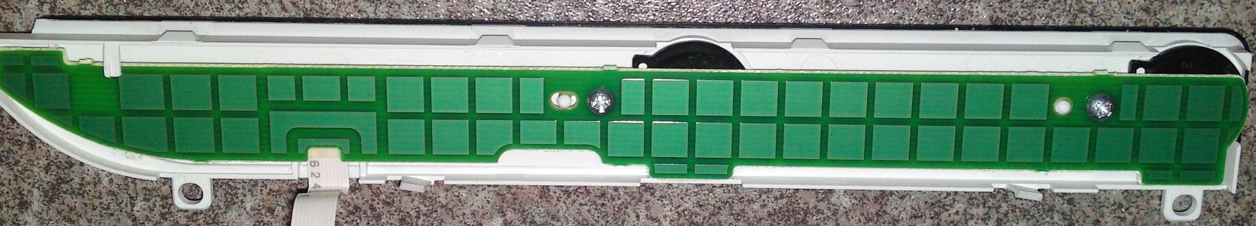
The photos was good enought to see all the lines of that "misterious leds", now that i painted on top you cant compare with what can be seen on the real photo, but well... im 99% sure is like that
But at this point there are so many labels, pins, etc... that is needed to verify a couple of things
The pins marked as SYS
The 2 black components with 6 pins each are 2 "dual transistors"... this means each led is controlled by a transistor, and syscon is connected with the "base" pin of 4 transistors, this pins are marked as SYS in the transistor, in pink color
So... in total there are 4 SYS pins in the transistors (that seems connected together)... and near the connector there is other SYS pin
You need to check with a multimeter if the SYS solder point near the connector (the side of the component marked with a black arrow) is connected with the others 4 SYS pins in the transistors (the multimeter configured in continuity should make a "beep" noise)
LEDS pins alternative solder points
Also, make this same check in the pins of the leds, and the points i marked with the letters of a compass (as example NE- means North-East led pin -). There are several, check in between the ones with the same names
The value of the resistors
In one of the photos (not the one i used in this image) can be seen better how are labeled, but are not completly clear, i have some doubts, what i can see is:
Resistor connected to
NE+ = 16E (mark) = 1430 ohm (resistance)
Resistor connected to SE+ = missing in action
Resistor connected to
NW+ = 751 (mark) = 750 ohm (resistance)
Resistor connected to
SW+ = 16E (mark) = 1430 ohm (resistance)
I used this table to find the values, but is better if someone checks it with a multimeter
https://www.hobby-hour.com/electronics/smdcalc.php
The value of this resistors is important because is one of the few things we can change and it gives some room for creativity :P
Also, because it gives an small hint about what sony was trying to do (the colors they was trying to achieve, the differences of color with HSW-001, and the posible variations of this circuit)
At this point i think DSW-001 had a previous version where this circuit was better and it was controlled by 2 syscon lines
Note there is a detail that doesnt makes sense... there is room to solder 4 resistors, but only to solder 3 diodes. The missing solder pads for the missing diode is because one of the leds is missing (but the solder pads for the missing led exists), and this is why SE- only have 2 posibles solder points, not 3 like the others
DSW looks like an intermediate step... and in HSW-001 they continued simplifying the circuit

")


 lol Also which setting on it for this? As I normally use it for circuit testing on cars.


")