PS3 (Research/Experimental) - NEC/TOKIN Capacitors Replacement - YLOD

Purposed Experiment: Defining capacitance tolerance: Would cost about $100 and risk a working PS3.
  1. Need a working PS3. Confirm PS3 is stable in the most intensive games. Standardize the testing procedure using GT6 or TLOU for the same amount of time at the same place, doing the same thing.
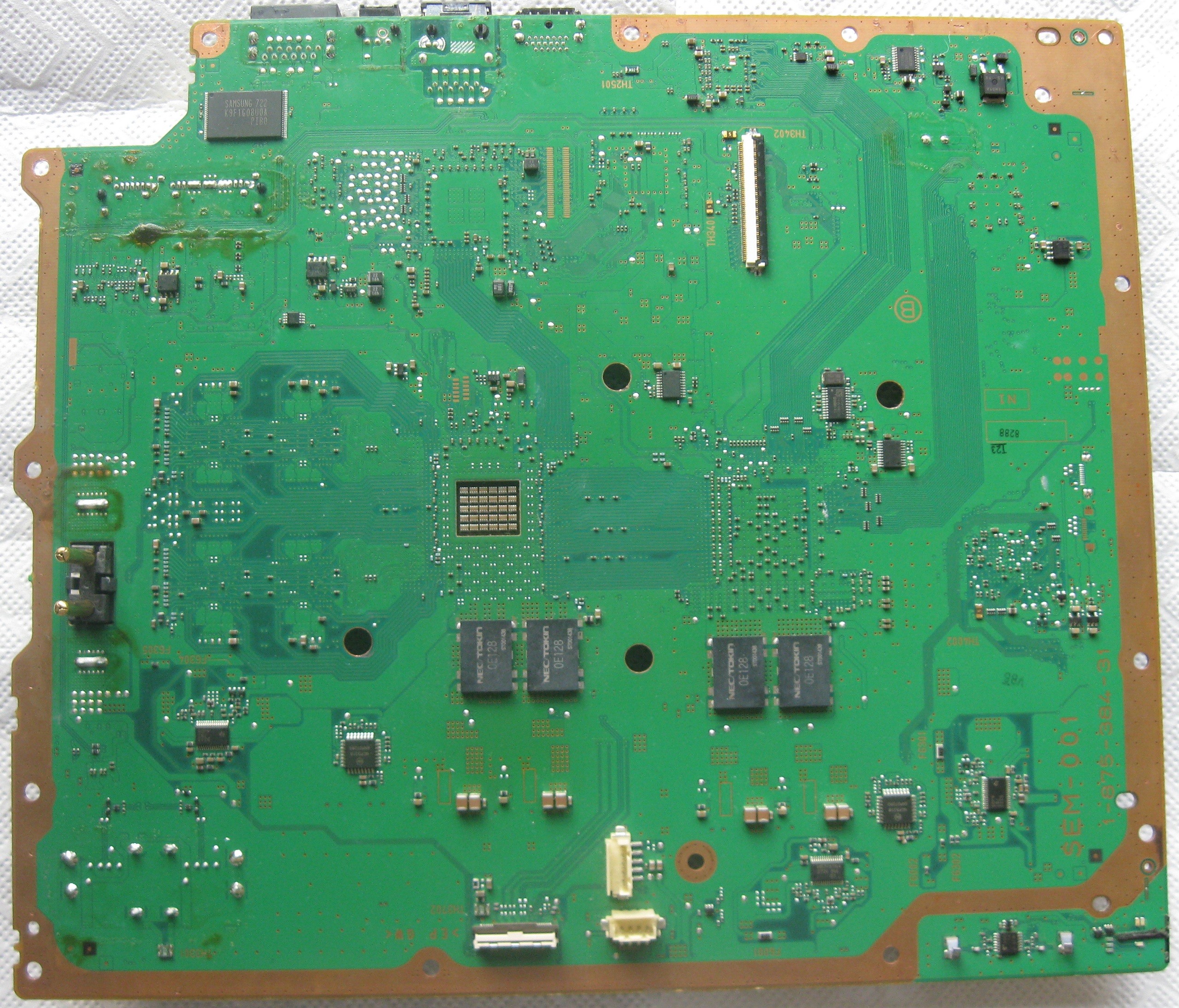
  2. Remove Tokins and replace with an ESR and Capacitance equivalent tantalum array. Stress test for stability to confirm a viable equivalent array. Choose very low ESR caps of small capacitance values, such that we only need to install one array and can remove one cap at a time. For example:
    • 22x 220µF 6.3v 5mΩ 6TPF220M5L = 4840µF 0.227mΩ ESR.
    • 14x = 3080µF 0.357mΩ ESR.
  3. Remove one cap. Repeat test. I don't think this can be done by just sniping them off, because you will bridge the +/GND in the process which will cause a YLOD. And probably cause them to explode or damage the board.
  4. Remove another cap, test…You can remove more than 9 if the system does not become unstable, but the ESR will climb above the tokin baseline. The results beyond that point are contaminated. You would need to install another tantalum array with an ESR low enough to rule out ESR from having caused the instability.
  5. If the console is stable with 14 caps, this would be the equivalent of each tokin having lost 36% of it's capacitance (from 1200uF to 769uF).
We know the console should continue to run and perhaps even be stable in game. @squeept already tested that by removing tokins 1-by-1 until the system became unstable. He was able to remove 5/8 before then. Unfortunately he went and nuked his social media so the videos are gone. What I would like to see are the Vpp measurements on CELL and RSX at the Vout near the tokins to try and define the point at which instability can cause a YLOD in high load situations...which brings me to another one of this thread's MYTH's:
  • A Random/Intermittent YLOD that occurs in games at certain points MUST be Bad NEC/TOKINs.
This MYTH is particularly dangerous, because it sound plausible. However, way back on page 100 @jupiterstar found that type of instability can be caused by a Power Supply that is not able to supply high loads reliably, but can handle normal loads:
PS3A: My own CECHA purchased from Circuit City back in 2007. Would suddenly turn off during games when it seemed like there was high GPU usage with YLOD (but could still turn it back on). Had it professionally reballed in 2012, but had same failure within 2 years of light use[...]I'm 99.9% sure it was a power supply problem[...]led me to think that maybe my PS3A had power supply that couldn't produce enough power when things were getting busy on screen. I temporarily swapped the power supply on PS3C with PS3A and was able to complete both the TLOU prologue and the bar fight scene in Uncharted 3, both of which I couldn't do before. I ended up buying another really cheap CECHA with GLOD (PS3D) and used that power supply for PS3A. Tested again and it still works. I ended up not changing capacitors and put back in original box and into storage.
So we need to be sure that Intermittent/Random YLOD are not a PSU first! Then we need to define the noise threshold that can cause instability. If it turns out that you can Play TLOU with equivalent to having just 3 tokins, then we have to consider the probability that BGA defects can cause this behavior too. It "seems" unlikely, but since when has that stopped reality?

BTW: this is just one small part of the larger post I'm working on. It just seemed relevant to post it now.
 
so another and probably last update on this CECHA00, i let it sit for 16 hours and it's currently running perfectly fine again, so i believe that this system is ultimately fixed 100% this machine never had GPU issues and since im using webMAN for dynamic fan control, the gpu never gets above 68c, and the fan never goes above 35% in dynamic mode lol, praise these delids


i dont see any reason to continue tests on this machine, since this PS3 will ultimately just be a PS2 at the end of the day & the heavy games work flawlessly so far
From what you have told us, that console has only had 1 thermal cycle. That's not good enough!

You never answered my question about time between tests. If you did all that testing yesterday without allowing to console to completely cool, between tests, then you never allowed it to have a full thermal cycle. It just went from one hot test to another.There is pent up stress in the motherboard that will relax over time and thermal cycles, kinda like how the earth's crust has pent up strain that takes time to release (earthquake). So, if you had a BGA defect it wouldn't show back up until the strain that's causing a mechanical reconnection is released. YOU NEED THERMAL CYCLES TO RULE THAT OUT.

BTW you have a history of leaving out details and making contradicting posts. When I'm done scrutinizing this thread I'm gonna ask you to clarify you console history, so prepare for that.
that seems like too much work for my care right now, i dont have the time unfortunately to do this long thermal cycle stuff, whenever i have time sure and ill make a follow up post
im just making posts sharing my successes or failures im not saying that this forum is 100% truth im going by my own experiences and such, you're probably right about the A00 who knows i personally just disagree with you here. none of my posts say that my repair is the definitive fix, im again just going by my experience with what i do and maybe others have the same experiences too
 
Last edited:
People look at positive results with hopeful eyes. They're desperate for an easy fix and laser in on every positive result as "proof" the MYTHs are true. Those of us who have been here for long enough to know better, have a responsibility to be careful with what we say. We need to document our tests fairly, so that a false positive can be identified and we don't mislead anyone.
Over and over, @squeept and I have been saying Thermal Cycles are KEY to knowing when a console is experiencing a BGA defect. If you had a bad tokin and the console is now fixed, these are ways to rule out a BGA false positive.
  1. Reball first (not going to happen unless your @squeept)
  2. Pressure test:
    • If instant or 2-5s YLOD: Press down on the RSX heatsink with steady firm pressure while boot.
    • If random/Intermittent YLOD try the coin trick or add a weight to the heatsink to increase pressure so you don't have to press down down the whole time.
    • If no change, it doesn't rule out BGA.
    • If it boots or becomes stable, then you have a BGA defect.
  3. Thoroughly test after the mod with Thermal cycles, before calling it fixed!
    • 1 hour in GT6/TLOU (hot stress test)
    • 2 hours off (cool down period to allow the board to relieve pent up pressure and settle).
    • Repeat about 5-10 times.
  4. Wait and see:
    • Report success, inspire a bunch of noobs to wreck their consoles, then find it didn't work when it fails randomly 3 months from now. This tactic is easiest and will get you the most likes, but is a dirty trick against the people of the world.
I don't think it's hard to shut the console off after an hour of testing and go watch a move while it cools. If you choose option 4, you should expect to be called out.
iu


I'll admit I was annoyed that you ignored my question and posted all about how the console was stable in the Hot tests. I think you're celebrating too soon.
:grenade:
Stress testing is important, but without a cool down period, it's meaningless. Worse it's misleading...which is why I had to put a stop to that:
:banana:

It's constructive criticism, don't take it personally. As you said, you've learned alot as you've gone on to gain experience. That's totally fair. Me too..lol!
well for a temporary update, i have let the system cool for two hours, played GT6 for awhile. so that would be 3 cycles then now, it seems fine, ill report again when i hit 5 thermal cycles, sorry again if i was kinda cocky, i completely understand your point here. any more data you want from this unit?
 
Super happy to hear testing is going well! Let's hope it keeps up...believe it or not I'm rooting for the fix. I do have a couple more questions.
  1. What gauge are those conductors? @squeept posted this chart on page 114 that's super helpful for deciding how many and of what gauge are needed. If you're going to stick with 4 conductors, I would use at least 16AWG (15A worth of pwr transmission). Residential codes in the US (probably similar elsewhere) have a 16A breaker. Most devices are capped at 15A (sustained draw) for safety. While a 12v 384W PSU can theoretically deliver 32 Amps, it cannot sustain that for long or it would trip the breaker. So my suggestion is to figure 15A sustained is the absolute max that these wires will have to conduct.
  2. Did you use hot air to install those TaPol caps, or just the soldering iron? If you used alot of heat, it could have pent up a lot of strain on the board and take longer to relax. This is the main theory why the heat trick works for a few months only, then stops. The more heat applied to the area around the CPU/GPU, the more likely a BGA false positive. I mean, up to a point. Obviously, if you keep heating you'll break the BGA or reflow it.
1. i used some old wire, i believe 23AWG wire. not entirely sure because it doesn't say on the wire, but its pretty thick, and i did send a photo of the work i did, 4 wires on the top side of the mobo,

2. no heat was used at all during the install or removal of the tokins, just prying and time lol


also semi update, played BO2 non updated so on V 1.00 or whatever
and the game froze and the system rebooted automatically so i don't believe thats Tokin related just bugs, played fine after that.
 
I just made an interesting discovery... I've been spending a lot of time getting familiar with my new, cheap-o scope and how it behaves. Since its output doesn't quite match higher-quality scopes, I decided to create my own "apples to apples" comparison. I removed all the caps from the cell (both top and bottom), but I left just the bridge in place. I also left all the RSX caps in place. Once i did all that, I did a ton of measuring between the two sets, until I was pretty sure I came up with my own set of "good signal" (the ones taken from the RSX) and "bad signal" (the ones taken from the Cell, because there weren't any caps :) ). All measurements are taken at 500mV/div, and 1uS/Div.

So here's the baseline "bad signal" from the Cell. You can see how jagged it is
FIIyJyM.jpg

FIIyJyM


And this is a baseline RSX signal. I'm calling this "Good" (the assumption being that my scope just doesn't have the resolution to read it any better than that). It looks very clean... it goes up, stays there and then goes back down.
6bSDGW2.jpg

6bSDGW2


Once I had those signals all documented (and I measured them at least 50 times over the last few days, just to ensure consistency), I proceeded to add caps back into Cell. For every cap installed, I mounted the power supply back on, and did a read with the same parameters.

Here's the "cap map"
BZZo2xE.jpg

BZZo2xE


So here's 1 cap added. The signal looks mostly like the baseline, but it's slightly cleaner -- those gaps between the peaks are mostly gone, and that's with just one cap
6Y4kf0u.jpg

6Y4kf0u


And then, from caps 2-8, the waves were pretty much the same! The gaps and the Peak to Peak are very consistent.
2rvLJ4U.jpg

2rvLJ4U


By this point, I ran out of space on the "near" side of the Cell, so then I added cap #9 (see the map cap above). Much to my surprise, once I added #9, the signal was almost as clean as the RSX baseline! Huge difference between #9 and #8
OXlPyaX.jpg


OXlPyaX


Adding caps 10-12 cleaned it even further. Every time I booted it, there was a little bit of noise that was difficult to capture. Probably adding another cap will fix it. My RSX has 15 caps 470uf caps, and the Cell has 12. Either one goes well above the 4800uf provided by the tokins.

11 caps -- even cleaner! but it has a bit of noise at the beginning
QnBnLfH.jpg

QnBnLfH


12 caps -- has a bit of noise at the beginning also, but it's just as clean as with 11

9Mkd7AI


Here's the link to the entire collection -- https://imgur.com/gallery/0xeDIRL
9Mkd7AI.jpg


So what's my conclusion? I don't think adding a 9th cap "made all the difference", because there was no difference whatsoever between having 2 and 8 caps (which is why I didn't bother posting them, but I can if anyone is interested). I think the difference is that I placed #9 on the "far" side of the rails, along with the caps that were on the "near" rail. I think that we need caps on both sides for us to get "clean" signals. That's just one theory, though! here's some others

* I reached a "minimum" amount of capacitance, and the signal "normalized". The tokins originally provided 4800uf between the four of them (4x1200uf). 8 caps at 470uf each adds up to 3760uf, and the 9th brought it up to 4230, which is not quite the original 4800uf, unless the "normalization magic" threshold is 4000uf. I highly doubt this theory, though.
* It's also possible that my baselines are meaningless!
* I might repeat this experiment later, but this time placing the caps on evenly on both near and far rails until I get clean signal... This would prove if the distribution of the caps is as important as this experiment suggests. This is tricky, though, I murdered 2 caps during removal because they're so freaking tiny and I don't have a heat gun.
On Page 118 @marciolsf performs some very interesting "cheap oscilloscope" measurements. He installs B case TaPol caps 1-by-1 on the Cell, starting with all removed. He mistakenly says say's they are 470uF, which threw me for a loop today. Looked up KEMETs coding system and eN8 (which can be seen in his pic) means 330uF 2.5v, which I think are the ones he used on on his previous attempt (page 98). So they're actually 330uF 2.5v 9mΩ.
  • Interesting jump in noise reduction between caps 8 & 9. Looking at his pattern of cap installation, cap 9 corresponded to the first cap he placed on the Vin side of the TOKIN rails after filling the Vout side with caps 1-8. Electrically that "shouldn't" matter.
  • Results:
    • 0 = +0uF = 275mVpp
    • 1 = +330uF (9mΩ) = 262mVpp
    • 2-8 = +660-2640uF (1.125mΩ) = 225mVpp
    • 9 = +2970uF (1mΩ) = 0mVpp (noise is visible though, scope doesn't read it)
    • 10-11 = +3,630uF (0.81mΩ) = 0mVpp (noise cleaned steadily until flat @11)
    • 12 = +3960uF (0.75mΩ) = 0mVpp (slightly more noise than 11, not significant)
...I reached a "minimum" amount of capacitance, and the signal "normalized". The tokins originally provided 4800uf between the four of them (4x1200uf). 8 caps at 470uf each adds up to 3760uf, and the 9th brought it up to 4230, which is not quite the original 4800uf, unless the "normalization magic" threshold is 4000uf. I highly doubt this theory, though.
I think you were right all along buddy! Sorry I'm just now getting to this. This is why I wanted to wait until I had caught up before posting, because new posts shed light on old ones. I think you were on the right track with this experiment, like I was purposing earlier. My method controls for ESR, your's didn't but there's still some good data there. I was expecting a more gradual decrease in the noise too. But remember when I said the RLC in the second stage filter is "tuned" to 4800uF? Well that would need to have a buffer zone to allow for variances in the tolerance of the NEC/TOKIN capacitors, which are (+/-)20%. 20% of 4800 is 960uF and 4800-960 = 3840uF.

Worst case scenario, 4x nec/tokins could come off PS3 manufacturing line adding up to 3840uF. So the filter still needs to work at that capacitance. To account for some loss due to heat and age, SONY's engineers probably threw in an extra 5% margin for reliability. So call it 25%. That means that we should see the filter begin to reduce the noise completely around the -1200uF mark. In other words the filter could loose up to 1 tokin's worth of capacitance and still work. Engineers like round numbers so this makes sense in my mind.
  • What's that number? 4800uF-1200uF = 3600uF
  • What was your number, before the filter reduced the noise? 3630uF
giphy-gif.19243
Damn @marciolsf ! You did that with an e-bay special? I would love to see this experiment repeated with a better scope and confirmed on the upper limit of the capacitance too. +25% = 6000uF. Above that the noise should get worse to a certain extent. Perhaps not bad enough to matter, but not ideal (based on the RLC tuning). @squeept you interested? I'm still working my way through this thread and documenting it. That project has my hands full ATM otherwise, I'd try it.

EDIT: yeah the scientist in me is crying foul. Just because I found a pattern in the noise (litterally this time), doesn't mean it's real. So yeah, we should temper our reaction. But that's a pretty suspicious coincidence! It doesn't mean the console will YLOD or anything, but it does give us a theoretical explanation for instability starting at that point. One based on numbers and evidence instead of maybe's! So it's progress!
 
Last edited:
I got a question. I bought 2 Broken CECHC04 on ebay. Both got an ylod. when I power on first ps3 it take some seconds, than YLOD. I replaced one RSX nec against 4 tantals works great again.

The second PS3 same model got the ylod direclty 1 second after turning on. I made the same procedure checked everything twice, but Nothing changed. it take same amount of time, no longer waiting til the YLOD like it should and said in this tutorial. (btw great tutorial). Im very soure that i didn't do anything wrong. IS there a chance that an CPU CELL nec tokin is causing the ylod? is this also a possible fault for an ylod? does a faulty CELL nec also causes a ylod?

I just do these repairs on trivia or curiocity, so I don'T whant to cut out more nec'S and install even more tantal caps (aren't that cheap for me) and waste more time and at the end the cell can't be the problem so Im asking before I brake out Cell Nec's
well you could always buy 20 tantalums and remove all the NECs, 10 tantalums for CELL & 10 for RSX, thats what i did with my A00. it probably wouldn't fix anything on that system but it's possibly worth a try
 
On Page 118 @marciolsf performs some very interesting "cheap oscilloscope" measurements. He installs B case TaPol caps 1-by-1 on the Cell, starting with all removed. He mistakenly says say's they are 470uF, which threw me for a loop today. Looked up KEMETs coding system and eN8 (which can be seen in his pic) means 330uF 2.5v, which I think are the ones he used on on his previous attempt (page 98). So they're actually 330uF 2.5v 9mΩ.
  • Interesting jump in noise reduction between caps 8 & 9. Looking at his pattern of cap installation, cap 9 corresponded to the first cap he placed on the Vin side of the TOKIN rails after filling the Vout side with caps 1-8. Electrically that "shouldn't" matter.
  • Results:
    • 0 = +0uF = 275mVpp
    • 1 = +330uF (9mΩ) = 262mVpp
    • 2-8 = +660-2640uF (1.125mΩ) = 225mVpp
    • 9 = +2970uF (1mΩ) = 0mVpp (noise is visible though, scope doesn't read it)
    • 10-11 = +3,630uF (0.81mΩ) = 0mVpp (noise cleaned steadily until flat @11)
    • 12 = +3960uF (0.75mΩ) = 0mVpp (slightly more noise than 11, not significant)

I think you were right all along buddy! Sorry I'm just now getting to this. This is why I wanted to wait until I had caught up before posting, because new posts shed light on old ones. I think you were on the right track with this experiment, like I was purposing earlier. My method controls for ESR, your's didn't but there's still some good data there. I was expecting a more gradual decrease in the noise too. But remember when I said the RLC in the second stage filter is "tuned" to 4800uF? Well that would need to have a buffer zone to allow for variances in the tolerance of the NEC/TOKIN capacitors, which are (+/-)20%. 20% of 4800 is 960uF and 4800-960 = 3840uF.

Worst case scenario, 4x nec/tokins could come off PS3 manufacturing line adding up to 3840uF. So the filter still needs to work at that capacitance. To account for some loss due to heat and age, SONY's engineers probably threw in an extra 5% margin for reliability. So call it 25%. That means that we should see the filter begin to reduce the noise completely around the -1200uF mark. In other words the filter could loose up to 1 tokin's worth of capacitance and still work. Engineers like round numbers so this makes sense in my mind.
  • What's that number? 4800uF-1200uF = 3600uF
  • What was your number, before the filter reduced the noise? 3630uF
giphy-gif.19243
Damn @marciolsf ! You did that with an e-bay special? I would love to see this experiment repeated with a better scope and confirmed on the upper limit of the capacitance too. +25% = 6000uF. Above that the noise should get worse to a certain extent. Perhaps not bad enough to matter, but not ideal (based on the RLC tuning). @squeept you interested? I'm still working my way through this thread and documenting it. That project has my hands full ATM otherwise, I'd try it.

EDIT: yeah the scientist in me is crying foul. Just because I found a pattern in the noise (litterally this time), doesn't mean it's real. So yeah, we should temper our reaction. But that's a pretty suspicious coincidence! It doesn't mean the console will YLOD or anything, but it does give us a theoretical explanation for instability starting at that point. One based on numbers and evidence instead of maybe's! So it's progress!

lol! I really should go back and edit that post... you're correct, those were 330, it was my previous set that was 470. Even then, I seem to have enough caps in place to at least reach that threshold. There definitely seems to be a pattern here, which is what I'd originally set out to determine. There's a few variations of the experiment that would be interesting to test:

* As you noticed, I placed most of them in vOut. In theory it wouldn't matter, but it would be interesting to reverse that and start setting them on vIn instead.
* I only tested them on the Cell side. It would be interesting to test on the RSX side as well, probably starting with vIn.
* I didn't have enough caps on hand to test them to the true spec of 4800uf, and I think that would give us the most complete picture -- I think you're right about the buffer, but maybe it's smaller than 20%.

And yeah, I'd love to get a real scope, I think I maxed out the abilities of the ebay special (and I used that little guy *a lot*), and then recreate the tests and see what I get. Maybe in a few months, who knows?

It would be mostly just for science, though, since I'm fairly convinced that I need a reball and I doubt I can get anyone to do it -- the board is still in pretty good shape, I never did any hot air anything to it, but it's obviously been worked on. If I could rule the solder balls out, it would be more likely that we could adjust the caps until we get to the magic working range.
 
well you could always buy 20 tantalums and remove all the NECs, 10 tantalums for CELL & 10 for RSX, thats what i did with my A00. it probably wouldn't fix anything on that system but it's possibly worth a try

So a YLOD can be in theory also caused because of a defective NEC on CELL side? Or would a power loss on CELL side do not cause a YLOD? that was my main question. If it can be, so I would try ordering mor tantalums and even change them on CELL side.
 
So a YLOD can be in theory also caused because of a defective NEC on CELL side? Or would a power loss on CELL side do not cause a YLOD? that was my main question. If it can be, so I would try ordering mor tantalums and even change them on CELL side.
yes, the necs can make it not boot if they fail on The cell side also
 
Capacitor Cheat sheet.png
I'll get back to this later...
@Naked_Snake1995 claimed the NEC/TOKIN capacitors are prone to fail in the initial post. It has been reiterated over and over at neausium ever since. 124 pages later @db260179 said:
"The NEC tokin defects has been known for a while and was heavly reported when toshiba had to recall alot of laptops to replace them."
People believe a YLOD is waiting around the curve to murder their backwards compatible console. This has prompted a few users to ask if it would be a good idea to risk destroying a perfectly working console as "preventative maintenance." Obviously that is a TERRIBLE idea! The fact that anyone would even think of it necessitates that we backup a second and see if the Tokins are really about to die.

Since everyone has been operating under the assumption that it's a fact, I decided it would be a good assumption to start investigating. This it one of the best ways to get at the truth of a matter. Question the assumptions made. I'm not saying it isn't true. What I am saying, it that no one has really questioned it and it is causing people to try and fix a problem that may not be there. So it's been on my list of things to investigate for awhile now.

How do we know this claim is true? We need something concrete. The only thing that makes me think there might be something to this is that NEC/TOKIN was a joint venture between NEC and KEMET, and KEMET caps suck! I avoid them like the plague. Since KEMET had 51% voting equity in NEC/TOKIN that immediately makes me think they suck. But that's just my bias against KEMET, I'm a Panasonic fanboy…lol! That doesn't objectively mean the TOKINS are bad caps prone to failure.

Today I started by trying to find any information online about this. There was a class action lawsuit against NEC/TOKIN for price fixing and Toshiba had a voluntary recall of laptop batteries due to fire hazard, but I couldn't find anything about defective capacitors! If anyone wants to do some more digging or knows where to find any good articals that outline why proadlizers are a flawed technology, please share it. I'll admit, I didn't dig very deep before I found something I can't believe no one else noticed. Hint: it has to do with the image in the soiler above, but I'm getting there. Keep reading...

One of the lines of evidence users on this thread have pointed to as evidence is that SONY removed them from later model PS3's:
  • That must mean that the NEC/TOKINS are bad (T or F).
That could be true, but it doesn't make it so all by itself. Maybe they weren't needed. The slim models began moving to tantalums starting with the CELL side on the DYN-001 in 25xx models. It's important to note that model has HF bypass caps populated on the motherboard and 7x470uF TaPol caps. The HF MLCC are 36x 0.1uF on the RSX/CPU, and 24x 10uF? on the CPU (which previous models lack). That coincided with the move to a smaller processor manufacturing process. The Cell_BE CPU was reduced to 65nm starting with the SEM-001 (G models). That was also when SONY removed PS2 compatibility and the Cell_BE 36x 0.1mF HF MLCC bypass caps. G models still had the 90nm RSX GPU and both have NEC/TOKINs, but the CPU's MLCC bypass capacitors are unpopulated. It has been mentioned before this may mean that the lower power draw or smaller mnf. Process reduced the need for them. Or they were deemed unnecessary and removed as a cost saving measure. Also, the number of switching DC/DC VRM was reduced from 3 to 2 on the CPU. That changes it's RLC characteristics and suggests that the only reason for the extra one was for PS2 HWBC. Also the APS231 power supply was more efficient since it didn't need to operate as close to its maximum output power (285W). Therefore, G models should be more reliable. If they are not, then maybe the tokins are failing.

And that's when I got lost and became confused - Just like you are now...lol! So that's why I made this:
PS3 CPU&GPU Bypass capicitor comparison chart.png

I have one last claim to evaluate. One I didn't even think to question. Are we sure that SONY actually did switch to Tantalum capacitors? How many of the later revisions actually have them? All you have to do is look at the chart above and answer it. Now it took me all day to make this, so you better appreciate it! Now onto the "Earth shattering" discovery I have made...

There are only 2 models of PS3 that have replaced the NEC/TOKINS with Tantalum Polymer. How do I know this? Because I went to the PS3 dev wiki and scrutinized every picture on the website. Then I went through my spreadsheet of this thread and scrutinized the motherboards and capacitors people have been "assuming" are Tantalum. To my SHOCK, most of the later models, and many of you are using Aluminum Polymer capacitors all along! This should come as no shock, however. Did you know that the NEC/TOKINs were Aluminum Polymer capacitors? Makes sence that they would replace them with AlPol then huh?

Here's some other interesting things to note:
  1. Every Fat model from A-Q used 4x 1200uF 2.5v 1.5mΩ NEC/TOKIN proadlizers (0E 128) on the CELL_BE CPU.
  2. The first console SONY replaced the NEC/TOKINs on was the 20xx model DYN-001 motherboard. And that was only a partial replacement. The RSX was still using 4x 1000uF NEC/TOKINs. The CPU used 7x 470uF 2v 6mΩ TPF series TaPol Pannasonic (2R5TPF470M6L) caps. This is also the first model to do away with the switching VRM (IP2003APbF, IC6104-6 on a COK-001). And they also added 22x MLCC high frequency bypass capacitors, 10 of which are on the CPU itself and can be seen inside the square hole on Side B of the motherboard. They are not present on the VER-001, which preceded it. That model still has tokins suppressing the switching noise. So the combination of linear VRM and TaPol + MLCC array of bypassing caps was enough to handle noise suppression.
    DYN-001-fuses-thermistors.back.jpg
  3. SONY did away with the The RSX's switching VRM (IP2003APbF, IC6202&3 on a COK-001) starting with the J models (DIA-002). This was also the first Model to feature the 65nm RSX and 4x 1000uF 2.5v 1.5mΩ NEC/TOKIN proadlizers (0E 108). The previous models were all 90nm and used 1200uF tokins. Notice that this switch didn't require any extra MLCC caps, since they were just reducing capacitance. This must mean that the smaller manufacturing process was either less vulnerable to coupling noise, required less power during momentery voltage dropouts, or both.
  4. The first model PS3 that required extra MLCC caps (12x I'm guessing 10uF?) was the 21xx (SUR-001), which was the first RSX to make the switch to 7x 470uF 2v 4.5mΩ SF series AlPol Panasonic (EEFSX0D471E4). Yup, that's right! Aluminum Polymer, not tantalum! The only model PS3 that actually used Tantalum capacitors on the RSX was the very next 25xx model (JTP-001).
    JTP-001_%28top_view%29.jpg
    JTP-001_%28bottom_view%29.jpg
    In fact they changed course very quickly and went back to AlPol mid-model with the 25xx (JSD-001)
    JSD-001_%28top_view%29.jpg
    JSD-001_%28bottom_view%29.jpg
  5. Evedently SONY decided AlPol was better (Cheaper?) than tantalum. Either way, they quickly moved to all Aluminum Polymer for the rest of the PS3 lifespan. Yup, you heard that right! Only 2 motherboard revisions actually have tantalums capacitors on them!!! Instead, they went back to the same thechnology that the tokins are...
:rolling:

Now, that little nugget of "HOLY SHIT!" may actually mean that that, yes indeed the tokins were prone to failure. Why change to between 6-8x AlPol caps to do the job of 4x TOKINs? Especially since doing so requires using 10uF MLCC caps in addition, to filter out the high frequency noise the proadlizers would have otherwise suppressed! Either the combination was cheaper, or the tokins were faulty. Now, before you go and say they must have been cheaper, 1st don't assume! Second, that class action lawsuit against NEC/TOKIN I was talking about earlier, was about price fixing. And it covered 2002-2016. Maybe SONY didn't want to pay NEC/TOKINs inflated prices and it was indeed cheaper going this route...IDK. I haven't looked up the BOM prices. So I'm not actually finished answering this question, but I did think it was worth a post to share my findings about the AlPol caps.
giphy-gif.19243
There are some more really interesting things I've noticed from that spreadsheet too. Such as the fact that SONY used between 6-8x 470uF caps, that they seemed to change their mind a few times, and that the switch to TaPol/AlPol coincided with the removal of Switching DC/DC voltage regulators. This may have some importance to the "Frankenstein Phat PS3" thread. I'm curious if that may explain the CG reset being tied to ground....maybe not, but there's definitely differences in the power delivery HW on BC models compared to all 65nm and 40nm models. What that means for the swap...IDK. I'm still reeling from this realization and theres alot to unpack.

So I'll leave it here for now.
 
Last edited:
@RIP-Felix One of the things I found when I pulled one of the only set of bad caps I found was that they hadn't lost any capacitance. I have literally never seen a TOKIN out of spec for capacitance or ESR. So I don't really see any point playing around with those experiments, especially on the CECHA01 consoles I usually have that will work with a coke can full of motor oil as a filter cap. And I'm seeing that I may have been wrong about the noise/voltage increase when swapping over. Next time I replace them all (will be at least a week, I ran out on the last swap and am waiting for more) I can ADD the tantalum one by one and grab you some images. But I think this kind of deep dive only needs to happen on non-BC consoles.

There's some weird degradation of the polymer that none of us can figure out (my current pet theory is that the layers appear to be spot welded together, and I think the spot welds may be failing in some way). Where did you find what the exact polymer in the TOKIN was, btw? I remember not seeing that anywhere I looked. Is it in the datasheet and I'm just illiterate?

I agree that all of that information in the last post is meaningful, but the problem is we'd have to have access to Sony engineers to explain why it was meaningful. Otherwise, it's trivial to just handwave it all away with a "standard changes with a new revision" as they looked at currently available parts, prices, and technology each time. I mean, just like pharmaceutical reps going from doctor's office to hospitals hawking their new drugs, I assume there are sales reps on the road all day hitting up the major manufacturers with a Powerpoint about how their new DC/DC converter is 2 cents cheaper than the competition and lowers design footprint by 3 square millimeters while being 0.5% more efficient! Boom, new part in the next revision.
 
Last edited:
ok after some time my cechc return to ylod. i use a broken ps3 board that never bother to fix and take out some tandalums found accross that board rated at 330mf i put in paralel 2x330mf to ylod console that im looking to fix nothing then 3 in paralel nothing again. looks like its time for the push trick to rsx but how to doit properly?
 
Yeah, good questions.
  1. There's some weird degradation of the polymer that none of us can figure out (my current pet theory is that the layers appear to be spot welded together, and I think the spot welds may be failing in some way). Where did you find what the exact polymer in the TOKIN was, btw? I remember not seeing that anywhere I looked. Is it in the datasheet and I'm just illiterate?
    Here's the link to Panasonic's Conductive Polymer Aluminum Electrolytic Capacitor (SP-Cap) Product Catalog. Search (CRTL+F) for "EEFSX0D471E4" and you find the cap I think it is. It's the lowest ESR variant, with 2v at 470uF. Process of elimination. And yes I went through the entire catalog one page at a time to match the caps as bet I could. What exact product# SONY actually used and whether or not Panasonic still makes it, who knows. However, I am sure its an AlPol because they all have a solid grey bar to the right of the landscape text markings. Also, the code matched up perfectly. That's how I know the "d" means 2v of AlPol. Panasonic's TaPol caps have a white bat with a + in the middle and the text is marked in portrait. The voltage code is the same, luckily. So that's easy to figure out.
    capacitor-cheat-sheet-png.30328
  2. I agree that all of that information in the last post is meaningful, but the problem is we'd have to have access to Sony engineers to explain why it was meaningful. Otherwise, it's trivial to just handwave it all away with a "standard changes with a new revision" as they looked at currently available parts, prices, and technology each time. I mean, just like pharmaceutical reps going from doctor's office to hospitals hawking their new drugs, I assume there are sales reps on the road all day hitting up the major manufacturers with a Powerpoint about how their new DC/DC converter is 2 cents cheaper than the competition and lowers design footprint by 3 square millimeters while being 0.5% more efficient! Boom, new part in the next revision.
    In this case every change to the second stage filter coincided with a change to the VRM.
    1. SEM-001 did away with the 36x 0.1uF MLCC caps that used to populate side B on the motherboard in the area above the CPU tokins. And apparently they weren't sure about the change, because they left the pads there, unpopulated.
      SEM-001_Bottomside.jpg
      This change coincided with the first DC/DC SW VRM being removed (from 3 to 2). Also that's when the moved to the 65nm CPU. Were they unsure if it would be unstable or not and wanting to leave the door open to re-populate them if so? They DIA-001 should answer that for us. If the pads are removed, then the change worked and they felt comfortable enough to close the door.
      DIA-001_Side-B.JPG
      This picture has too much glare to tell if those are just VIAs or if the pads are still there.
      Maybe someone with an H model can confirm? It is clear enough to see the MLCC's are still gone. That change is permanent, they only appear on the BC 90nm CPU models.
    2. SONY never removed the 1200uF tokins until moving to the 45nm CPU. That's when they did away with the other 2 SW VRM. This move necessitated the addition of 22x 10uF? caps.
    3. And so on...I detailed this in my previous post and you can see for yourself in the spreadsheet I made.
  3. The point is that every time SONY messed with the second stage filter it coincided with a CPU change. This required them to redesign the second stage filter to optimize it for the new PWR requirements. The whole point of the bulk capacitors is to suppress switching noise. No switching, no switching noise. That would allow SONY to remove the proadlizers and go with more conventional filtering (AlPol + MLCC). However, and this is one of the more important points, they didn't feel comfortable doing so for the RSX until they went to the 40nm version. They got rid of the sw VRM with the switch to 65nm, but only decreased the capacitance of the TOKINs, they did not replace them with Tantalum or Aluminum Polymer!
    • My guess is they started with the CPU because it's workload is more stable, the same reason it doesn't need reballing. Once that experiment worked, they moved onto the RSX. When they were able to remove all the switching VRM on the RSX, they were content for the next 6 models (J-Q, DIA-002 and VER-001).
    • Sony went to Panasonic TaPol caps again starting with the CPU (20xx, DYN-001) and then they Went to all AlPol (both CPU & GPU) with the 45nm RSX (21xx, SUR-001).
    • Then they experimented with TaPol on the RSX with the very next revision 25xx (JTP-001), but quickly abandoned that idea mid-model, going back to AlPol with the 25xx (JSD-001). Perhaps Tantalum was too expensive, or no more reliable. Either way, SONY abandoned tantalum pretty quickly - Probably because of cost.
  4. Now, like you said @squeept , these design decisions add up to nothing more than a logical reiteration of the second stage filter, necessitated by the switch to processors with a smaller manufacturing process. They were able to remove the IP2003APbF (or change to different switching VRM...IDK. I'm basing the column "SW VRM" off the presence or absence of IP2003APbF viable in the pictures on the wiki. I don't have the schematics or motherboards to see what VRM they actually switched to. Nor can I actually read the writing on the chips in most of those pictures. Maybe some other switching DC/DC converter? Or linear VRM? IDK!!!). None of this means that the tokins are a flawed technology.
  5. However, when I got burned buying those crappy KEMET yellow TaPol caps I ran home to mother Panasonic! Maybe SONY returned to mother after getting burned on NEC/TOKIN. There's not enought here to build that narrative, but they may have.
@RIP-Felix One of the things I found when I pulled one of the only set of bad caps I found was that they hadn't lost any capacitance. I have literally never seen a TOKIN out of spec for capacitance or ESR. So I don't really see any point playing around with those experiments, especially on the CECHA01 consoles I usually have that will work with a coke can full of motor oil as a filter cap. And I'm seeing that I may have been wrong about the noise/voltage increase when swapping over. Next time I replace them all (will be at least a week, I ran out on the last swap and am waiting for more) I can ADD the tantalum one by one and grab you some images. But I think this kind of deep dive only needs to happen on non-BC consoles.
Haha...um...well, okay. I have been working on another long ass post about just that theory, so let's table that for now. I'll get back to you...Just remember you asked for it...lol!

As for trying the test again I would try using AlPol instead. It might be cheaper to harvest them from a broken slim or super slim. Or use the same TaPol that SONY used in the very few models that actually used any. And dont forget the 22x MLCC' on the cpu and 12x on the RSX. They apparently were needed for the HF noise that the tokins would otherwise have suppressed. @Workz_777 began building a replacment tokins back on page 118, but I'm not sure if he ever optimized that method, Nor if he was able to scope it. That's where I currently am in my re-reading of this thread.
Hiya, well "re-use" NECs is not really an option for the long term. Because they are no longer being made. The only stock left is old stock from when NEC/Tokin made them originally back in the past. Now there is the option to buy this old stock from sellers in China, until all that runs dry.

But yeah for the short term. But how long will the "new" old NEC capacitors last anyway, 1 year, 2 years, and then what?

We really need a solution with Tantalums, but Tantalums alone are not enough, even Sony added about 12 x small MLCCs in combination with every 7 x 470uF for each processor. But by then Sony had reduced the PS3's power consumption (Watts) by half.

If we want to copy what Sony did, when they replaced the NECs with Tantalums in later board revisions, then we would have to roughly base it from this example:-

Sony's version, no NEC/Tokins...

PS3 board using 80W - 100W (average Watts) needed the following:-

CELL - 7 x 470uF Tantalums + 12 x MLCCs*
RSX - 7 x 470uF Tantalums + 12 x MLCCs*

*Could be MLCC values of:- 0.01uF, 0.1uF, 1uF, or 10uF, or maybe a combination.

In theory, based on the above example, a COK-01 board, which consumes 200W (average Watts) and even has a maximum of 380W consumption (original PSU), would need something like a combination of 14 x 470uF per processor + (at least) 12 x small MLCCs per processor. Without the MLCCs, it could be the Tantalums are not enough to filter the power line efficiently for the sensitive processors to work, and the PS3 would likely give ylod.
He is right, we cannot simply copy what SONY did for the later models, because those filters were optimized for 40/65nm chipsets. So I still think the sweetspot is 4800uF. So 10x 470uF. The problem with that is that the ESR is 0.600mOhms instead of the tokins 0.375mOhms. They may heat up more, but they should be okay. SONY aparantly wasn't worried about the 1.167mOhm ESR of using 7x470uF 6mOhm caps, but those chips also don't pull as much current as the 90nm do.
 
Back
Top