PS3 (Research/Experimental) - NEC/TOKIN Capacitors Replacement - YLOD

A ha, so it does exist! So that should mean you can retrieve pictures, game backups and music off the HDD if the console dies, yes?

I'll have to test it out when I get home. I have been looking for a more reliable way to transfer lots of files without failing FTP transferrs that take forever. And if it works the way I hope, I should add it to my tutorials as a disclaimer for those just looking to retrieve important data (assuming its stored on the HDD). It would save them lots of troubleshooting and expense that could be avoided.
The encrypted partition is nothing special, just UFS + encryption, as long as you have the eid_root_key to decrypt the data, the ps3 hdd0 partition should be accessible through various means.
For instance, there are some commercial recovery tools (supporting UFS+encryption) that work fine.
Linux/BSD can also be set up to access that partition.
And of course there is the read-only ps3 hdd reader (with an old GUI by aldostools), nobody could be bothered so far to extend support to writing.
 
Ah, so you can read but not write. Well that is good enough for data recovery.

The key sounds familiar having worked on OG xbox. I remember needing to dump that before I could lock/unlock it. And I vaguely remember there being a tool for mounting the filesystem. Sounds like a similar process for PS3 then. Any tutorials available? I'd like to read up on it.
The console's eid_root_key can only be dumped if lv1 is exploited therefore reading/writing to an internal ps3 hdd using another device is currently only possible for hdds coming from CFW compatible consoles.
The day the hypervisor gets defeated through a new exploit, it will be possible on all models.
It might be feasible to dump the eid_root_key with only a lv2 exploit (like in HEN) but there is no such dumper available publicly at the time of writing.

The wiki provides details about the Linux way to mount the ps3 hdd0 partition.
https://www.psdevwiki.com/ps3/Mounting_HDD_on_PC
There are also a few threads dedicated to this topic here in which you may find updated files & tips.
 
Last edited:
Which caps did you choose? This is kinda important. Low ESR is the problem with cheap caps and $10 seems too low. Usually a full set of 24x costs $30-50. But I always buy from mouser, digikey, or arrow. Ebay and ali express are selling low tier binned caps or leftover from large production runs. So they could be +/- 30% or as good as the guaranteed 10-20% caps you get from large distributors. Its a crap shoot. It's probably fine, just measure before installing to be sure it's near rated spec.

Of course, if your tokins are fine, you are more likely to do more damage than good. Be sure to have a good temperature controlled iron, not a RadioShack special. And a good thick tip. Otherwise put the board on a preheater. Alternatively you can use hot air to help drive the heat of you iron in. The PS3 ground plane will sink heat like crazy...IT'S NOJOKE! Not as easy as it looks! So I would only attempt it if you're sure its needed.

So before you actually go through with the tantalums instal, I would dump the SYSCON error codes to see if you have the tell tale 1002 of bad tokins or a 3034 indicating BGA. If BGA, just do the frankenstein before potentially hurting things with the tantalums. It's your console though, so light it on fire and roast a wieny in cancer smoke if you want to. Its your property...lol!

well okay i have news i tried the rsx pressure thing and it doesnt worked, tried like 3 times and i dont want to keep doing it cuz maybe i can make damage on the BGA solder
Of course i have a SMD station with hot air and soldering iron
Well like i said the worst scenario is replacing the tokins for no reason, if i dont have success like i said ill try to find someone to do frankestein or a lead reballing, i dont care about losing the tantalums money so i will not do the syscon read if is not 110% needed

Can you send a scheme of how looks a COK-002 with all tokins replaced with your 3x method?
and please if you can send me here or pm some links to see examples of the capacitors you use ill thanks it a lot !

My main goal is to get my shit backed up of course, but if i can fix the shit out without reballing it its welcome lmao

The console was never treated badly in terms of temperatures so thats why i suspected a lot about this tokin shit, i already burned up some fats so with this one was a first day webman mod modded fan curve and good maintenance
The only place where i used a static fan speed was on PS2Emu and it was turbine mode 90/100%
 
Last edited:
The console's eid_root_key can only be dumped if lv1 is exploited therefore reading/writing to an internal ps3 hdd using another device is currently only possible for hdds coming from CFW compatible consoles.
The day the hypervisor gets defeated through a new exploit, it will be possible on all models.
It might be feasible to dump the eid_root_key with only a lv2 exploit (like in HEN) but there is no such dumper available publicly at the time of writing.

The wiki provides details about the Linux way to mount the ps3 hdd0 partition.
There are also a few threads dedicated to this topic here in which you may find updated files & tips.
thanks u so much dude ill try it but like we know to get this shit working i need to boot up the console some minutes at least
 
well okay i have news i tried the rsx pressure thing and it doesnt worked, tried like 3 times and i dont want to keep doing it cuz maybe i can make damage on the BGA solder
Good call, it wasn't working, no need to damage it. Basically all this test does is confirm a BGA defect if it works. We can't rule an RSX issue out though, so it's not meaningful when it doesn't work. So unfortunately it doesn't prove the BGA is fine, only the SYSCON can do that.

Of course i have a SMD station with hot air and soldering iron
Well like i said the worst scenario is replacing the tokins for no reason, if i dont have success like i said ill try to find someone to do frankestein or a lead reballing, i dont care about losing the tantalums money so i will not do the syscon read if is not 110% needed
I'm not saying that's what your issue is. I am saying you should do the SYSCON. No it's not 110% necessary, but If you are going to do something as drastic as replacing the tokins, installing 2 tiny jumper wires and running a script is trivial.

Can you send a scheme of how looks a COK-002 with all tokins replaced with your 3x method?
and please if you can send me here or pm some links to see examples of the capacitors you use ill thanks it a lot !

My main goal is to get my shit backed up of course, but if i can fix the shit out without reballing it its welcome lmao

Sure bro, if you want to jump strait to the tokins I have some suggestions to make that endeavor easier...

I recommend a Palisades arrangement like this:
etpsf270m6e-palasades-arrangment-most-efficient-jpg.31092

The picture above was using 270uF B-Case TaPol, but it wasn't effective. I would use at least 330uF B-case caps if I were to try this again, but I don't recommend them anymore. Instead, I recommend 3x 470uF Panasonic 2R5TPE470M7 TaPol caps. 2mm height max! I am using resistor legs for the conductor above, but they may not be thick enough to handle all the current if you were to replace all the tokins. Maybe leave one or add jumpers. Be sure to cover the RF shield above them with Kapton tape to prevent shorting.

I am finally home now and will resume work on my Tantalizer revision. EDIT I just uploaded and shared it on OSH park. I hope to have it released soon. However, I think the palisades arrangement above cheaper and easier overall. My board just has a much larger copper plane to conduct the + rail, so there is no need to worry about jumpers and gauge.

The console was never treated badly in terms of temperatures so thats why i suspected a lot about this tokin shit, i already burned up some fats so with this one was a first day webman mod modded fan curve and good maintenance
The only place where i used a static fan speed was on PS2Emu and it was turbine mode 90/100%
Reducing delta T will reduce BGA stress and extend reliability, but it will not prevent RSX issues form occurring. I'm not convinced there isn't another flaw in play. The underfill used around that time is known to be an issue. @DeadEnd linked a paper about it I haven't had a chance to read yet, but I've looked into it before and He's not the first to bring it up. We know that DIE bumps go bad.
 
Last edited:
PS3 Tantalizer - Beta Release (v0.9b)
(Order or Download from OSH Park HERE)


Tantalizer Installed.jpg
Notes:
  • If you choose to use this PCB, you are doing so at your own risk! I cannot be held responsible for any damages. Although at this point they have been used successfully for several years without issue, assuming they were soldered correctly and appropriate capacitor choices were made.
  • This PCB is designed to make it easier and safer to attach polymer/MLCC capacitors to your PS3. Replacing the NEC/TOKINs IS NOT guaranteed to fix the problems you are experiencing. You must properly troubleshoot your console to decide if this mod is right for you.
  • MLCC pads are meant for 0805 case size.
  • You must choose 0.8mm board thickness in the options during checkout. This ensures it'll fit underneath the RF shield when you reassemble the console.
  • You must buy 2mm height capacitors or shorter. This ensures it'll fit underneath the RF shield when you reassemble the console.
  • Polymer pads are for 7343 (7.3 x 4.3 x 1.9mm, LxWxH). You can use other types of capacitors that fit this footprint, such as aluminum polymer, tantalum polymer, etc. However, they must be low ESR/ESL processor decoupling capacitors. The PCB takes up 0.8mm of height, so caps need to be low profile (less than 2mm). Each one should be less than 9mΩ ESR, 4.5mΩ ideally.
  • Example Capacitors: these are only examples, use the specifications to shop around for the best prices.
    • 3x 470uF 2.5v 7mΩ Panasonic 2R5TPE470M7 TaPol caps.
    • 1x 47uF 10v X5R 0805 MLCC (Example)
    • 1x 22uF 10v X5R 0805 MLCC (Example)
    • 1x 10uF 10v X5R 0805 MLCC (Example)
    • 1x 4.7uF 10v X5R 0805 MLCC (Example)
    • 1x 2.2uF 10v X5R 0805 MLCC (Example)
    • 1x 1uF 10v X5R 0805 MLCC (Example)
    • Total cost = About $25 for a set of 8x tantalizers
  • You do not need to buy the MLCC capacitors. The 470uF capacitors are enough on their own. However, the MLCC capacitors help to attenuate the higher frequency noise component up to around 2MHz, better mimicking the NEC/TOKIN proadlizer it's meant to replace. This is probably overkill on PS3's with 1000uF tokins. I still recommend using 470uF caps, because 3x 330uF is only 990uF and may not be enough. It's better to have more capacitance than less, but not too much more. The MLCCs are more needed on 90nm CPU/GPU early models (A-H). They have noisier switching VRM and higher load, which requires more decoupling than later models. Use them if your tokins are OE128 models. You probably don't need them otherwise.
  • You can download the Gerber files from OSH Park if you perfer to have another board house manufacture your Tantalizers. Just be sure the board is 0.8mm thick.
Pictures:
Side A.png Side B.png

Note: The following pictures are of v0.3a I made with 7x MLCC pads. I decided to remove C10 because there was too little clearance between +/GND. v0.6b linked above will not have 7 MLCC pads. It has 6. And instead of a long edge for the GND connection, it now has 4 plated vias. These changes where needed to make it easier to manufacture. But the following pictures will give you a general idea of what they look like.
TOP.jpg BTM.jpg
Castellated Edge 1.jpg Castellated Edge 2.jpg

Here's one of v0.6b with Aluminum Polymer Caps.

20220530_144349.jpg
Discussion:

People have asked me if the ceramic caps are necessary and how to calculate the right ones to use. I use KEMET's K-Sim to model the frequency response curve of any capacitor combination, to decide what values best attenuate the higher frequencies TaPol caps aren't as good at rejecting. The tokins were better at that. However you can use MLCC's to push the combined frequency response curve down. The MLCCs are not needed, we have confirmed the 470uF caps are sufficient on their own. But you can use them if you'd like to.

Here is an example of the frequency response curves:
Tokins vs Array.png
Tantalizer.png
 
Last edited:
Hi, I removed the two Nec Tokin cap located on top of the board which connect to the RSX as explained in this thread.
In doing so I misplaced a small capacitor circled in red.
Would someone know the capacitance value and maybe package size?
Thanks

Inkedmissing cap_LI.jpg
 
0.1uF tiny AF.

...but don't worry about it. That's part of a larger aray of 36 in parallel. 35 of them is fine and missing one wont have a big enough effect to make much difference.

EDIT. I noticed there are still the metal contact pads from the tokins still connected to the rails in your picture. Be sure to remove those.
 
Last edited:
Thanks for the info about the capacitor value and the metal contact pads.
I ordered the PS3 Tantalizer v0.3 from OSH Park but I am not sure to understand which MLCC value to choose for IC4 to IC9.
Thanks for taking the time to design the PCB!
 
I ordered the PS3 Tantalizer v0.3 from OSH Park but I am not sure to understand which MLCC value to choose for IC4 to IC9.
I used Kemet's K-Sim to model the frequency response curve of the array of capacitors I recommended in the release post above. An example cap is linked to, but I just chose the first one that cam up in the list, not a specific one. Any cheap cap of right capacitance, dielectric and voltage will be similar in performance. So choose the cheapest option. Or skip them entirely, you probably wont ever see a difference. The MLCCs are just on there for people who really want to add them for kicks and giggles. It better approximate a tokin in the simulation, but I haven't measured it the real world, where it counts. As stated, this is still experimental.

Here's what a tokin does (if you can believe the promotional flier).
Tokins vs Array.png

Here's a post I made awhile back explaining my reasoning for the tantalizer and MLCC array...
I would imagine if there isn't enough capacitance to smooth out voltage drops during peak loads, the console will likely just YLOD on boot during the POST process. It does a basic test on boot to see if the processors are alive and kicking. That's the rev-up you hear when you first start the console. It's not taxing like an intense game, but it's more than just idling in the XMB. So that really only leaves the noise component.

The noise is more variable. Noise spikes can occur at any time due to any load. If they occur at an important time, they'll interfere and eat up CPU cycles. If it gets bad enough, they'll cause a YLOD. So in @Pacorretaco's case the noise increase caused by removing half the tokins wasn't enough to cause an instant YLOD, but it surely would have caused the CPU/GPU to work harder (more heat) and probably would have caused a YLOD under stress (like a game). In the case of tokins losing capacitance, they steadily allow more noise in. So you can add tantalums like he did to replace the lost capacitance, but the reason we use 470uF is because they're impedance vs frequency curve (frequency response curve) has a resonance frequency centered at the correct range of the switching noise range. So yes, it adds back capacitance, but does so surgically targeting the noise frequency.

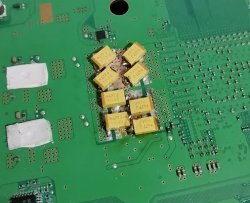
Here's an example of just 3x 470uF TaPol caps...
tantalum-alone-png.33429
The red box is the area of concern. from 100KHz-10MHz is the component of switching noise that the tokins are responsible for decoupling. Notice how the impedance curve pops out the top of the box? That means noise of 3MHz+ will not be reduced below 10mOhms (I chose that number to be safe, but can it be calculated as Z_target if you have the correct information). Here's an Oscilloscope image of the noise left over after replacing with just 470uF tantalum Polymer caps...
working-target-plateau-png.33432

The RSX (Blue) has 12x470uF TaPol caps and the CPU (Yellow) has 18x 270uF TaPol B-case caps. You can see that the remaining noise on the RSX has a frequency of 1.92MHz and an amplitude of about 10mVpp. Based on the K-sim above we were expecting it to be 3MHz, but real world doesn't match theoretical exactly. It was pretty close though. The frequency of the noise on the CPU is 2.63MHz and if you look closely there are 2 distinct amplitudes of noise. One 30mVpp peak followed by two ~20mVpp peaks. That's what I meant when I said there appears to be 2 distinct peaks when I combined having 470uF caps on the RSX and 270uF caps on the CPU. The K-sim of the 270uF caps shift their frequency response curve to the left. So they allow more noise through the "red box" above (target frequency). I "think" that explains why the frequency of the noise is different and why it's amplitude is higher. However, it's important to note that this noise is being produced primarily by the IOR switching voltage regulators and the CPU has three of them, whereas the RSX has two. So the RSX filter doesn't have to remove as much noise as CPU's does.

The above noise is fine. That combination of capacitors was stable in intense games, no problem, but I think I could do better. That's why I added MLCC pads to my Tantalizer PCB. Here's what the K-sim of my recommended combination looks like (3x470uF TaPol + 3x22uF MLCC + 3x10uF MLCC)...[
tantalizer-recommended-png.33431

That gets the combined frequency response curve below the 10mOhm threshold I'm shooting for. But notice that the capacitors I chose target the 1-3MHz frequency? That's the noise I measured! I think this is the easiest and cheapest solution, since you only have to buy 2 additional caps. It's easier to source them and to keep them separate while installing. However, the curve can be theoretically improved using this combination...
tantalizer-best-png.33430

...But it's more expensive sourcing 47uF MLCCs and keeping 6 different MLCCs separate during installation is annoying. It does look sweet on paper, but who knows if the real world performance is worth the added expense and headache. Also, it could result in worse performance, since it's doesn't reduce the 1-3MHz noise as much as my targeted approach does (theoretically. I still need to measure the results). EDIT: Here are the measurements for the tantalizers on the CPU...
target-plateau-normal-aqu-png.33433

Noise on the CPU went down predictably. It's well under control now, but there appears to be more noise on the RSX now. It is stable. Perhaps the RSX needs MLCCs also, IDK. It's possible that an anti resonance peak in the CPU side has amplified the noise in the RSX side, but it's still under the threshold and not causing problems, so I'll leave it alone until it does. However, it's up to you what you populate the PCB with, so you can play with the K-sim and come up with a frequency response curve you like.
Proadlizers have a ridiculously low impedance across a wide frequency range. It stays low into the higher frequencies that are hard to reach with traditional arrays (above 1MHz).

The reason this matters is because noise and ripple occur at different frequencies. Lower frequency ripple generated by the switching voltage regulators is smoothed out by Tantalums caps. Voltage ripple is what we are primarily concerned with. If it's large enough to cause a YLOD, the wavelength is so long it'll interfere with any normal signal, completely blocking it. Think of it like a train blowing its horn while your carrying on a conversation....
Your friend is saying, "The sun is...[CHOO]...when your...[CHOO]... And it's hard to...[Rumble...Rumble...CHOO...CHOO...Grind...Squeek...Skueek...Rumble...Choo...Choo...Rumble...Rumble]...Did you...[CHoo...Choo]...Dude! Did you hear what I said or was that train too loud?"
So low frequency noise just overpowers the signals and completly drowns them out.

The higher frequency noise remaining can interfere with signals, but it's more like someone screaming short randoms while carrying on a conversation.
"The sun is...[Ahh!]...when your...[A$$!]...outside and it's hard to stay dry. I like it when the...[$h!T!]...comes out and warms me up. Dude, did you hear what I said or was that guy with Tourrettes too loud?
You might have have missed a word or three, but can figure what was said because you heard most of it. It doesn't exactly work the same with a computer, but depending on what the information that was blocked by a noise spike all manner of issues can occur. The processor might have to resend data, or it could cause artifacts, freezes, and YLODs. Basically random a$$ Sh!T. So it needs to be decoupled.

Most people know a capacitor acts like a battery and delivers a little current when there is a voltage drop. But they have another property that's the lesser understood function. They provide a low impedance path to ground for high frequency signals. So instead of noise spikes entering the processor and interfering with the game, the noise can bypass the processor and go straight to GND through a nice low impedance capacitor.

That's the lesser know function of capacitors. Each capacitor has a frequency response curve like the ones pictured above. The V shape curve tells you what frequency noise it can decouple (bypass to ground). Combining capacitors with a V that's at 100KHz, with one that's at 150KHz broadens the frequency range that your "Array" can decouple. So usually there are many values of capacitors used to achieve a suitable frequency response curve for a given circuit. This way the noise floor is low enough for the circuit to carry on a nice easy conversation without trains or tourrettes getting in the way.
 
Last edited:
Can I check if someone has ever had this issue after replacement of the NEC/tokin?
Static image output on the screen
Screen freeze.jpg


If I put things into context:
The console was YOLD however was able to boot with green light followed by immediate triple beeping sound and red flashing lights.
So I decided to replace the 2 NEC/Tokin on top around the RSX.
The PS3 worked after that and was able to hold 20~25 min from cold boot but would eventually go back to YOLD state.
After inspection I could not see anything wrong with the 470uF capacitors then proceeded to replace the ones at the bottom.
During 1st test the console did boot to XMB but the screen quickly turned to garbage.
I am worried the RSX was damaged during the process.

Bottom.jpg
 

Attachments

  • Top.jpg
    Top.jpg
    81.7 KB · Views: 219
Can I check if someone has ever had this issue after replacement of the NEC/tokin?
Static image output on the screen
View attachment 35199

If I put things into context:
The console was YOLD however was able to boot with green light followed by immediate triple beeping sound and red flashing lights.
So I decided to replace the 2 NEC/Tokin on top around the RSX.
The PS3 worked after that and was able to hold 20~25 min from cold boot but would eventually go back to YOLD state.
After inspection I could not see anything wrong with the 470uF capacitors then proceeded to replace the ones at the bottom.
During 1st test the console did boot to XMB but the screen quickly turned to garbage.
I am worried the RSX was damaged during the process.

View attachment 35200
Long story short, you most likely need a reball. The bumps on the die could be bad too and a reball won't fix that. But the only way to know for sure is to reball and see, so that's the next path forward.
First problem I can see are the capacitors you chose are not low ESR/ESL CPU decoupling cap.

The second is the same mistake I made with PS3#1; that's when I first joined. The console booted and played for a day (the false positive period) before freezing with graphical arttifacting similar to yours (the WTF period). My ensuing struggle to figure out what went wrong was plagued by false beliefs and perpetuated by my desire for the NEC/TOKINs to be bad when they weren't. This was before we had the SYSCON UART for diagnosing if the tokins are actually bad. And unfortunately your experience is a common one. It can be avoided if more people knew about the SYSCON diagnostics. It's just that the myth about the NEC/TOKINs and the popularity of the false positive "YLOD Fix" videos on youtube, posts on Reddit and other forums have taken a life of their own. It's a situation where the lie is preferable to the truth and people choose to bury their head in the sand until it's too late.
 
I can order the 9mOhm version https://sg.rs-online.com/web/p/polymer-capacitors/7955834/ as the one linked is out of stock.
I did order the tantalizer v0.3 and parts for the SYSCON few days ago. Let's see if it helps otherwise I'll seek service for reball.
Thanks for sharing.
No, the one you linked has an ESR of 18mOhms. 9mOhms would be as high as I would recommend if using 12x caps. And that's already too high!

9mOhms / 12 caps = 0.75mOhms combined ESR.

NEC/TOKINs:
1.5mOhms / 4 caps = 0.375 combined ESR.

So an array of 12x 9mOhms TaPol caps will have a combined ESR twice that of the one they are meant to replace.

To achieve an ESR of 0.375mOhms you need 12x 4.5mOhm caps. They are only available in AlPol, which should work fine. In fact SONY switched to them in later models. TaPol were only used in transition models where they decreased the CPU from 65nm to 45nm, and again with the RSX from 65nm to 40nm, to be sure the consoles had adequate filtering. Subsequent models had AlPol. Evidently they concluded the advantages TaPol provide weren't necessary to justify the added ESR and expense.

The advantage to Tantalum is lower ESR for higher frequency noise. They don't heat up as much from that component of the noise. However, because AlPol can have a lower ESR at its resonance frequency, it's hard to know if either one has a distinct advantage until actually testing them in circuit. So in theory, TaPol should last longer and provide slightly better noise rejection. But in the real world, IDK. I have been meaning to do some tests to find out, but that's not super high on my list of priorities.
 
I previously ordered (8) Tantalizer v0.2b per PS3 for a total of (24) plus a few spares to rework the inappropriately high ESR capacitors I originally used, and get the PS3s back into proper spec. Along with this, I also ordered (24) of Panasonic 2R5TPE470M7 capacitors per PS3 for a total of (72) plus a few spares.

Before:
View attachment 35212

After:
View attachment 35211
I liked the way it looked before better!

Although the bridge wire is difficult to prevent bridging that way, I had trouble doing it that way as it kept melting the thermoplastic and shorting to ground. Eventually I had to start bending the wire up and over so that couldn't happen. Then I got fed up and made my own PCB. I'm not super proud of V0.2b. I don't like the castellated VIAs. They need trimming to remove burrs and don't look good when installed. It's and aesthetic thing for me. I know when the console is closed no one will see them, but I want it to look clean anyway. That's why v0.3b has castellated slots instead.

Another thing I don't like about 0.2b is that I tried to get fancy routing the signal path. I think it just made things over complicated. And I didn't know how to round the edges in eagle then, so there could be ringing and reflections. I'm concerned that its noisier than it should be. That's what I wanted to address with 0.3b. It's a "keep it simple, stupid!" approach. All the edges are rounded so there shouldn't be any ringing or reflection that could make it noisy. And the routing path is a short as possible.

I would recommend you get 0.3b from now on. Maybe replace the other ones if you haven't installed them already. They're cheap enough.
 
I can order the 9mOhm version https://sg.rs-online.com/web/p/polymer-capacitors/7955834/ as the one linked is out of stock.
I did order the tantalizer v0.3 and parts for the SYSCON few days ago. Let's see if it helps otherwise I'll seek service for reball.
Thanks for sharing.

Before you do that you should hook up the SYSCON and dump your errorlog. We should be sure that your console needs a reball first. When it had the YLOD it should have had 3034/4xxx errors indicating RSX issues, which include BGA defects. If so, then there's a good chance a reball will work. It's not a 100% chance though. And finding good BGA rework service is difficult and expensive. So good luck!
 
I would recommend you get 0.3b from now on. Maybe replace the other ones if you haven't installed them already. They're cheap enough.

Functionally, I don't think there's any major problems with the v0.2b, I'm going to keep them installed on the CECHA.

But I am going to order 18 of the v0.3b (8 for the CECHB, 8 for the CECHH and 2 spares) since the price is so low. Why not?
 
Back
Top