"(Not)Dead" C PS3 (NLoD?)

So @sandungas you say it can be a transistor huh?, makes sense, though I think I'm not going to attempt anything yet anyway.

The one with the red arrow looks the most suspicious to me. That pin goes to pin 5 of the PSU connector, I checked with multimeter.
On the thing it's printed "LCARKI"
Yep, is a dual transistor actually (internally his circuits probably looks "mirrored" because is the same thing repeated 2 times), take some time to review the "fix" i was sugesting in this post
https://www.psx-place.com/threads/cechg03-stuck-in-fan-test-mode.20453/page-2#post-161613
I dont understand what the chip IC4001 does, but i can deduce is dedicated to that special feature that detects the electricity fields of your finger when you touch ON or EJECT buttons
In the suggested fix i was cutting the VIN of IC4001 because it seems there was a problem related with it (maybe was fryed internally), or in his resistors/capacitors surrounding it, in few words... i was trying to bypass IC4001 because the touch sensistive feature was not working in that console
Basically... the output signals of IC4001 (that goes to the dual transistor Q4002) should work at the same voltage than the VIN of IC4001

The chip IC4001 (or a replacement of it) that deals with the "touch sensistive feature" only exists in PS3 fats (because the case)
But i bet the dual transistor exists in all PS3 models included superslims too

The nice thing is in your COK-002 mobo the dual transistor have a bunch of testpads around it, nice to check it (and for experiments trying to get the final proof that is fryed internally)
And yeah... just by how it looks, i would say your LCARKI is the dual transistor (Q4002)

Btw, remember you can desolder the dual transistor and "flip" it because is very improbable that it went fryed completly
The most probable thing to happen is to fry the internal circuits that belongs to the ON half, but the other half that belongs to the EJECT should be fine
* As a side note, I opened this thing mostly because it needed delid, and I saw something a bit interesting:
The memory chips on this RSX don't say Qimonda, but actually Infineon.
Maybe this was an early production unit made right before Qimonda split from Infineon. I don't think this appears in the wiki (Maybe because it's meaningless, at the end of the day it should be the same module).
But I wonder if this is something rare or something. I never saw this before.

Cheers
Im checking and you are right, there is no info in wiki about that infineon rsx-ram chips, interesting, not sure what to do yet, there are several wiki pages that could be affected by that


Edit:
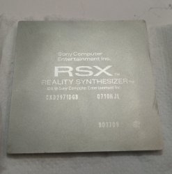
For wiki purposes... can you tell me the exact RSX model (etched in the IHS metal) that have the infineon chips ?


Edit2:
I just noticed your LCARKI have only 5 pins (not 6 pins like the one i was discussing in the other thread), so your LCARKI probably is a single transistor
 
Last edited:
Just fond the mistery about the infineon rsx-ram, is the same component than Quimonda HYB18H512322AF-14 but with a different brand, it seems infineon owns quimonda
https://en.wikipedia.org/wiki/Qimonda

There is a photo in wiki with the quimonda, but i also found another photo in reddit of another delidded motherboard like yours so is not so rare
ko13anvpl0x41.jpg
 
Here is the heatspreader picture

And yeah as I mentioned the module should be exactly the same, probably came out of the same place and the same people.
Just may be very early sample, from the time right before Quimonda separated from Infineon in 2006, so they printed the old Infineon brand.

Just something I had never seen before.
After all not everybody removes the heatspreaders

Edit: Just saw you added my picture to the wiki page. That's nice

(And btw if the picture of the IHS is not so clear, the number at the bottom right corner is a number 8, not a letter B)
 

Attachments

  • IMG_20210409_120350~2.jpg
    IMG_20210409_120350~2.jpg
    568 KB · Views: 58
Last edited:
Here is the heatspreader picture

And yeah as I mentioned the module should be exactly the same, probably came out of the same place and the same people.
Just may be very early sample, from the time right before Quimonda separated from Infineon in 2006, so they printed the old Infineon brand.

Just something I had never seen before.
After all not everybody removes the heatspreaders

Edit: Just saw you added my picture to the wiki page. That's nice

(And btw if the picture of the IHS is not so clear, the number at the bottom right corner is a number 8, not a letter B)
Thx for the phto btw, it surpised me a bit so see the brand infineon because there was not any mention of it in wiki
If you take a look at the different component providers used by sony usually they have only 2 (or 3 as most when they are doing some transition), is like they are covering his back by having 2 supplyers incase one of them have a problem. For the RSX RAM there was only mentioned qimonda, samsung and hynix (for the whole PS3 familly), so it was a bit shocking to see another provider with the weight of infineon used only in a very specific PS3 model
But now i realized qimonda and infineon was manufacturing the same components it makes more sense because it means sony was working with infineon for lot more time :)


Edit:
The CELL RAM that appears in this table (XDR system memory) made by qimonda probably was "printed" with the brand infineon on some PS3 models, im not going to add the name in the table in wiki because i dont have any proof, but yeah... probably is the same story
https://www.psdevwiki.com/ps3/Template:Motherboard_Components
 
Last edited:
Spoiler alert, the console is actually "working".
Check this old video I found:

Mine has same behavior. But I would like to be able to solve whatever problem in the standby circuit if possible, instead of running it like that, with the 12v active all the time.

So help would be appreciated. I guess if it's some IC I might be able to borrow a replacement from other boards I have, which maybe won't need it that much.

Alternatively, any ideas as to what bad things could happen if left like that? Guy from the video implies he left it like so, long term.

Thank you

Dude this totally works! I got this No Light of Death yesterday with a COK-002 after I tried some externalised PSU with alligator clamps. During the setup the daughterboard CSW-001 is holding on to the little flex cable so the power red light goes on and off sometimes I thought it was due to poor connection of the flex cable. However the red light doesn't turn on after I put everything back with the PSU on top. Checked the daughterboard voltage it got 5V on the 5V_EVER pin, but nothing works. Pressing the button, inserting a disc, nothing turns on.

So tried this method, initally with 1K resistor on the jumper wire, no success. The voltage reads on ACDC_STBY is below 2V. So as this thread described, today I lowered the resistor to 100 Ohm and flipped the switch, the red power light comes back and it can respond to your touch. After adding the 100Ohm resistor, the ACDC_STBY reads 2.55V, I guess still not quite to the "standard" but it wakes up the syscon+switch board at least.

One thing to note is, after adding the jumper wire, when you flip the switch on the back, you can hear a little click probably inside the PSU(a relay that turns on 12V output?) and the fan kicks in just for maybe half a second then stops. So I guess the 12V turns on when the mainboard isn't ready for sending any PWM signal to control the speed. Thus it start to spin when no signal is present, then stopped because for some reason the forced-on 12V "wakes up" the previously sleeping syscon/sb/fan controller ic.

I'm still wondering what could have cause this problem.

UPDATE: looks like a voltage regulator (IC6005 in COK-002 service manual) from 5V to 3.3V is malfunctioning. I can only verify it from probing its output, only 0.66V while the VIN and EN pin are all 5V. I don't have a hotair station to work on SMD parts so maybe update this later.
 
Last edited:

Similar threads

Back
Top